Help please!!
So I am always learning and my circuitry skills are getting better but I need help with this
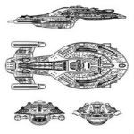
I am lighting a NX01 kit and I have the prebuilt circuits for the strobes but I want to make the circuit for the illumination LEDs
I have an old torch chip that caters for 24 LEDs to be attached in parallel with 1 resistor after the positive terminal,
What I want to know is if instead of having the 1 single resistor can I just wire up all LEDs to the board and then each led has it's own resistor?
Parallel circuit resistor requirements
Moderators: Sparky, Moderators
Parallel circuit resistor requirements
Check out my Borg Enhanced Voyager
http://www.youtube.com/watch?v=rKaMTm4Lvmk
http://www.youtube.com/watch?v=rKaMTm4Lvmk
-
USS Atlantis

- Posts: 2388
- Joined: Sat Sep 08, 2007 6:44 pm
- Location: Galaxy 217, Orion Arm, Sol System, Sol III, 44° 53' N 93° 13' W (Local coordinate system)
- Contact:
Yep - though I'd watch to see what resistor value it is
If it's a higher value, that means that more power (volts & current) are being "stopped" by it - and that also means more heat dissipation
One resistor dissipating a fair amount isn't going to heat up much - 24 resistors dissipating the same amount may generate enough heat to damage styrene
In a parallel circuit, 1 or 24 - each one will still have the same value ergo the same power/heat dissipation