
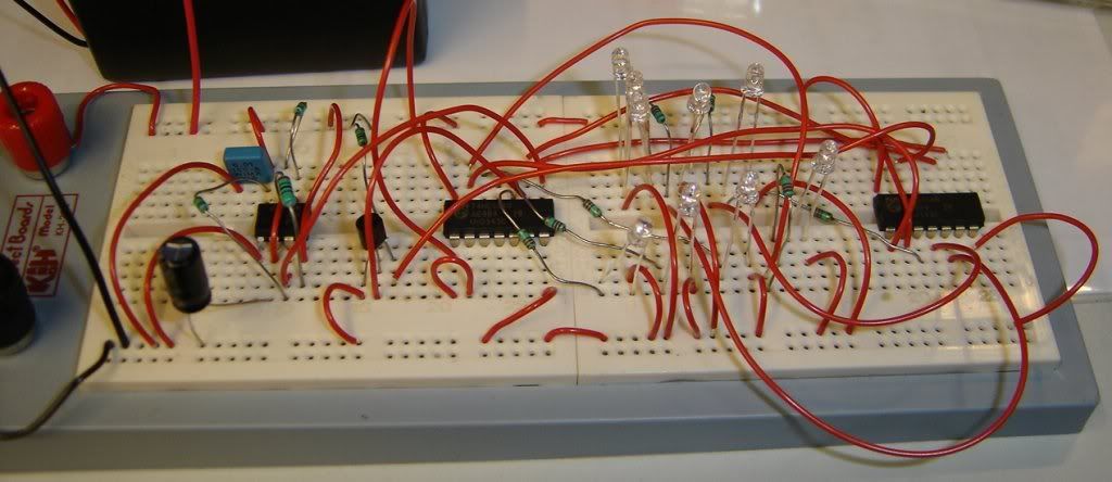
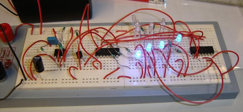
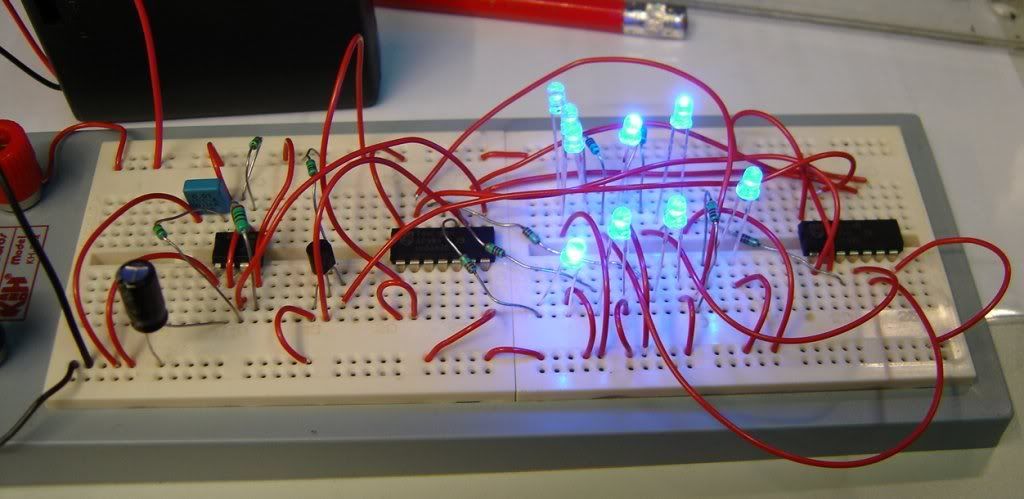
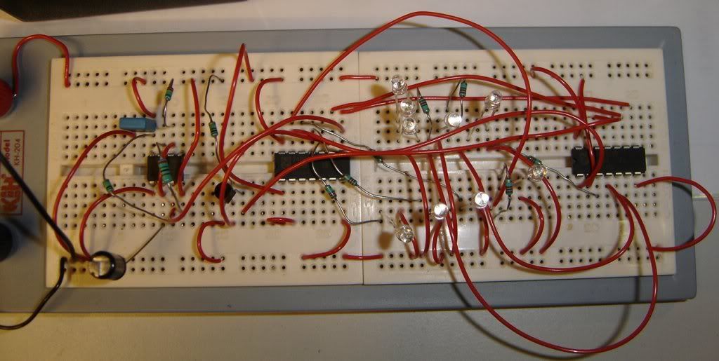
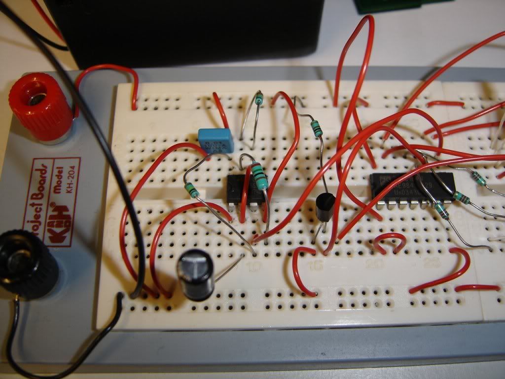
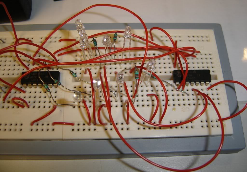
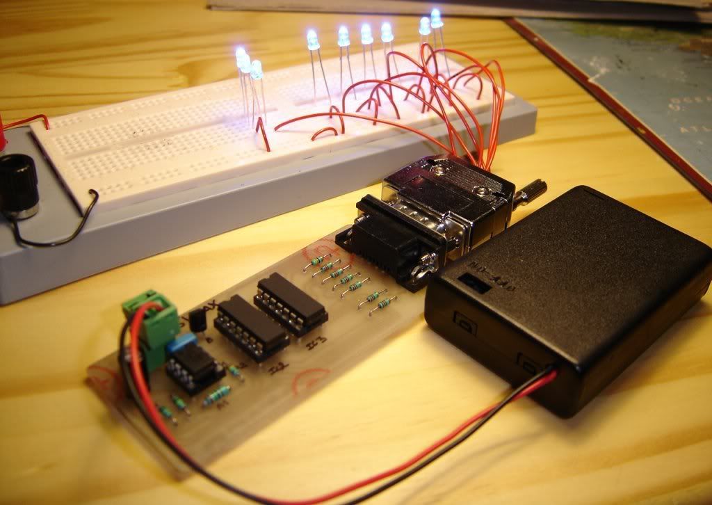
Here is the electonic schematic that i have develop and experiment on a lab-board.
This is to simulate the Stargate lighting sequence of the 9 chevrons, to be integrated in a full scrach of the gate.
A integrated circuit NE555 in astable mode at 1Hz frequency, rate of work 2 shift register 74HC164 to memory a logical "1" on these outs, for drive 9 Blue LED 3mm diameter; and fine, the register are "reset" by a NPN transistor for the sequence restart.
http://i6.photobucket.com/albums/y241/m ... C04365.jpg
http://i6.photobucket.com/albums/y241/m ... C04366.jpg
http://i6.photobucket.com/albums/y241/m ... C04367.jpg
http://i6.photobucket.com/albums/y241/m ... C04369.jpg
http://i6.photobucket.com/albums/y241/m ... C04370.jpg
http://i6.photobucket.com/albums/y241/m ... C04371.jpg
http://fr.youtube.com/watch?v=7dAhvhvV38o (sound added in the video, not on the circuit)
Here the components list :
Intergrated Circuits:
IC1 = NE555
IC2, IC3 = 74HC164
Transistor:
BF422
LED:
9x Led 3mm cristal Blue, 2000mcd, IF = 20mA typ. @ VF = 3,6VDC, 470 nm
Connectors (optional):
1x DB9 female
1x DB9 male
2 pin connectors to go to a 4,5V-6V max battery
tulip supports for IC
Resistors:
R1 = 1M Ohm
R2 = 220K Ohm
R3 = 100K Ohm
R4, R5, R6, R7, R8, R9 = 120K Ohm
R10 = 43K Ohm
R11 = 100 Ohm
Capacitors:
C1 = 1µF
C2 = 10nF
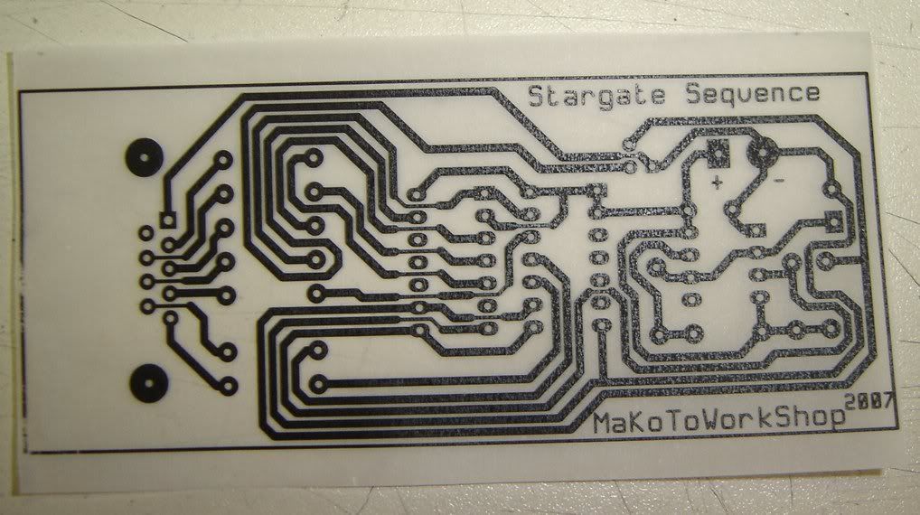
For the electronic epoxy card execution, you can follow http://www.abcelectronique.com/acquier/typon.html
http://www.selectronic.fr/article.asp?a ... .3304-9999
some sellers could do it for you ?
Or use a card with holes, to weld the components, and make the connections with wires between the components yourself
http://www.selectronic.fr/soussousfamil ... fam_ref=34
http://www.selectronic.fr/soussousfamil ... fam_ref=30
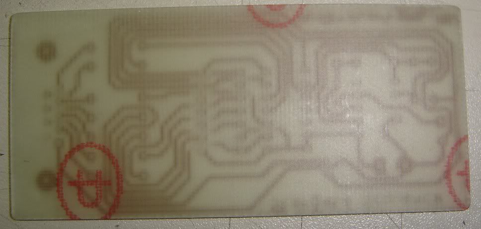
The typon print on a tracing paper
http://i6.photobucket.com/albums/y241/m ... C04382.jpg
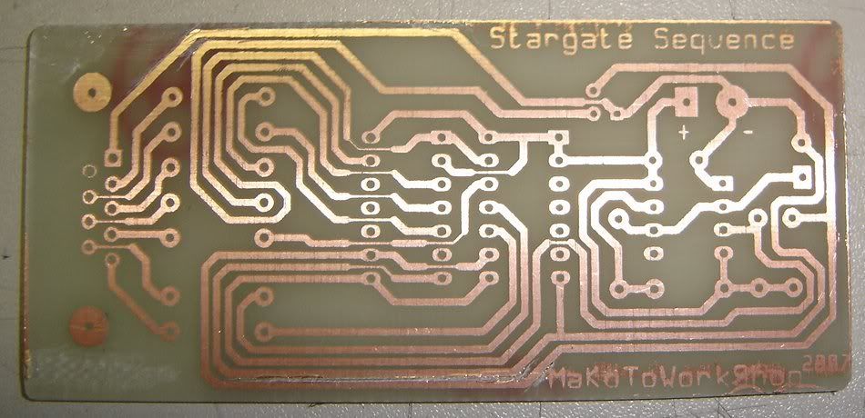
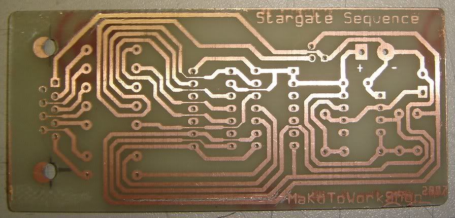
Result before drilling :
http://i6.photobucket.com/albums/y241/m ... C04375.jpg
http://i6.photobucket.com/albums/y241/m ... C04376.jpg
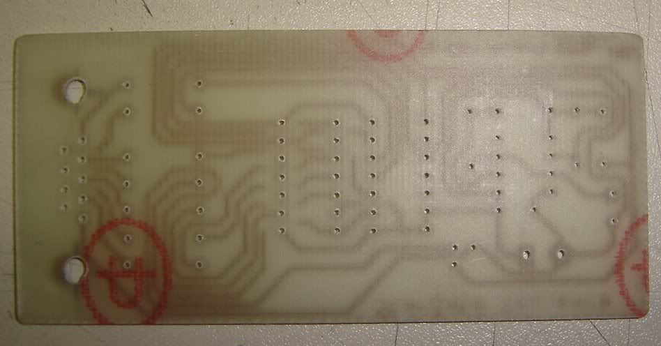
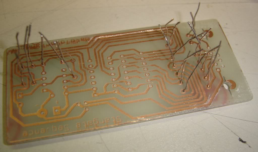
after drilling :
http://i6.photobucket.com/albums/y241/m ... C04377.jpg
http://i6.photobucket.com/albums/y241/m ... C04378.jpg
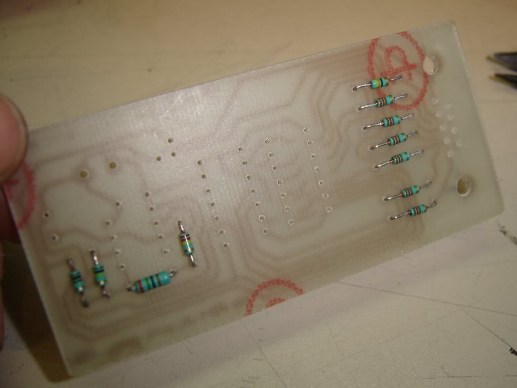
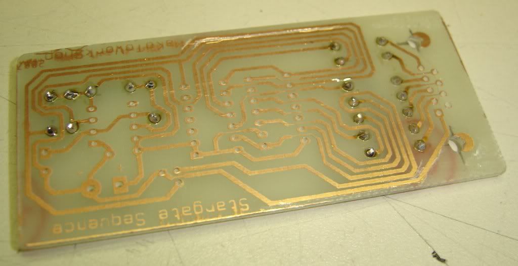
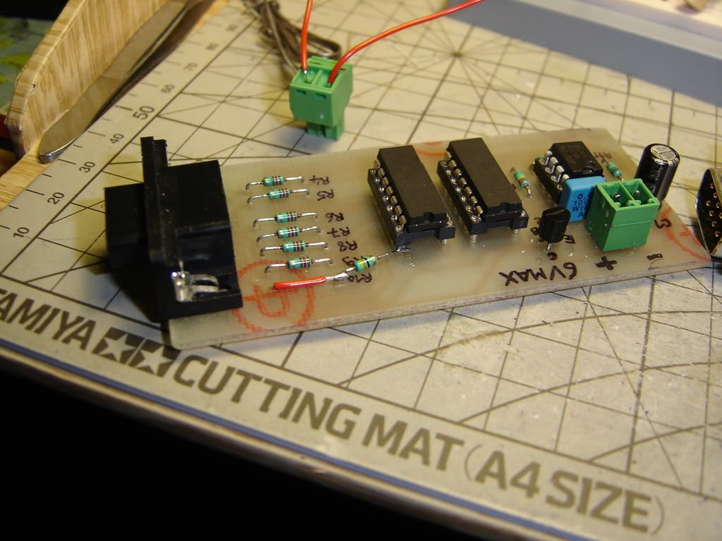
With the resistors, weld, and cut pin :
http://i6.photobucket.com/albums/y241/m ... C04379.jpg
http://i6.photobucket.com/albums/y241/m ... C04380.jpg
http://i6.photobucket.com/albums/y241/m ... C04381.jpg
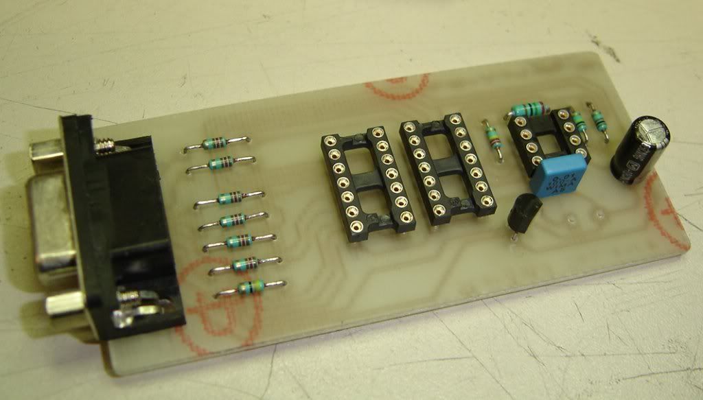
and all the rest components :
http://i6.photobucket.com/albums/y241/m ... C04383.jpg
http://i6.photobucket.com/albums/y241/m ... C04384.jpg
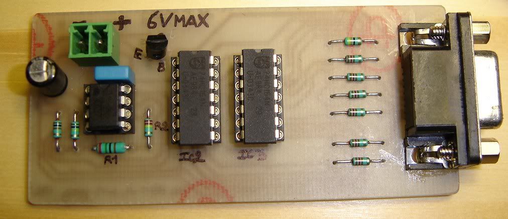
The connectors for battery and with notes, and the IC:
http://i6.photobucket.com/albums/y241/m ... C04385.jpg
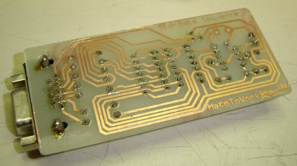
tada !
http://i6.photobucket.com/albums/y241/m ... C04387.jpg
http://i6.photobucket.com/albums/y241/m ... C04388.jpg
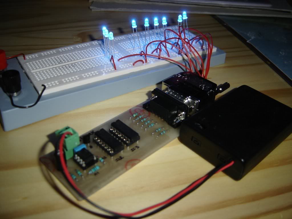
And here with a little modification, cause i was doing a electronic mistake who cause the 3 lasts blue Led not shinning in the good intensity.
http://i6.photobucket.com/albums/y241/m ... C04602.jpg
Some rights reserved
Job under Creative Commons by-nc-sa Licence
http://creativecommons.org/licenses/by- ... deed.en_US
Stargate Sequence whith 9 LEDs
Moderators: Sparky, Moderators
Stargate Sequence whith 9 LEDs
Last edited by MaKoTo on Tue Sep 02, 2008 2:56 am, edited 3 times in total.
-
en'til Zog
- Posts: 2405
- Joined: Fri Jul 12, 2002 3:03 pm
- Location: The Wilds of Northwoods Wisconsin