I built a 555 timer in an astable multivibrator configuration. I checked all the connections and it looks like it's hooked up right, but when I apply power the light just stays on instead of blinking. This is a common problem I have with this type of circuit, but I'm not sure what causes it or how to solve it. I already replaced the IC on the assumption that I fried it accidentally with static discharge (I'll have to get a static dissipative mat one of these days...), but it does the same thing. Is there something I can check to see what's going on with this circuit?
For the record, here are the components:
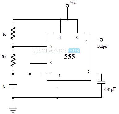
R1: 10K
R2: 1.2K
Diode: 1N4005
C1: 0.1 uF
C2: 0.01 uF
Vcc: 12v, through a LM7812 voltage regulator (the circuit will be 18v when all is said and done, but I'm using a 12v wall wart at the moment because the power supply isn't built yet)
The diagram I'm using: http://www.electronicshub.org/wp-conten ... brator.jpg
I also put a 1.5K current limiting resistor on the Vcc input and a 220 ohm resistor on the LED.
Why is my 555 timer not blinking?
Moderators: Sparky, Moderators
-
MillenniumFalsehood

- Posts: 16991
- Joined: Tue Nov 16, 2004 5:23 pm
- Location: Wichita, KS, USA
- Contact:
Why is my 555 timer not blinking?
If a redhead works at a bakery, does that make him a gingerbread man?
Ponies defeat a Star Trek villain? Give them a Star Wars award ceremony!
Ponies defeat a Star Trek villain? Give them a Star Wars award ceremony!

Re: Why is my 555 timer not blinking?
Hope my picture helps. Ignore the trim pot to the bottom right as that fades my torpedo tube for my d7.
http://i.imgur.com/LFO41ur.jpg
Additional thought. Are you trying to make a strobe blink? I use a signal diode in parallel to r2 for strobing, which gives the short duty cycle. No diode if just going for a nav light cycle.
http://i.imgur.com/LFO41ur.jpg
Additional thought. Are you trying to make a strobe blink? I use a signal diode in parallel to r2 for strobing, which gives the short duty cycle. No diode if just going for a nav light cycle.
“Life is pain, highness. Anyone who says differently is selling something.”
― William Goldman
― William Goldman
Re: Why is my 555 timer not blinking?
Without looking at in person and having an o'scope I can only offer this help.
The LED is blinking, but at an extremely fast rate due the RC time constant of of your timing resistors and capacitors. Try different values.
The LED is blinking, but the duty cycle (ratio of on/off times) has it mostly on with an extremely short off time.
The 555 chip won't work with 12V like you thought it would, try a lover voltage like 5V.
How is the LED connected to the chip? Try reversing its' polarity. If the LED is good it should go off when it is reverse biased. If is blinking at very fast rate you may be able to detect a faint glow in this configuration.
Find a friend who has an o'scope to look at it for you to see signals a meter won't show.
"Nothing to do now but drink a beer and watch the universe die."
"Basically what I do everyday."
I AM Spartacus!
I'm Batman.
Don't believe everything you see on the Internet!- Abraham Lincoln
Oh my God!! It's full of plastic peanuts!
Today is a good day to model!
"Basically what I do everyday."
I AM Spartacus!
I'm Batman.
Don't believe everything you see on the Internet!- Abraham Lincoln
Oh my God!! It's full of plastic peanuts!
Today is a good day to model!
Re: Why is my 555 timer not blinking?
Diode: 1N4005 Why do you need this? It's a rectifier to control high voltage surges from what I am reading.
“Life is pain, highness. Anyone who says differently is selling something.”
― William Goldman
― William Goldman
-
MillenniumFalsehood
- Posts: 16991
- Joined: Tue Nov 16, 2004 5:23 pm
- Location: Wichita, KS, USA
- Contact:
Re: Why is my 555 timer not blinking?
Yeah, hence the 1N4004 (It's a 1N4004, not 4005, btw). I want a strobe, not a nav light.
I'll probably need to take it to the school and use one of theirs.EVApodman wrote: ↑Sat Aug 19, 2017 10:07 am Without looking at in person and having an o'scope I can only offer this help.
The LED is blinking, but at an extremely fast rate due the RC time constant of of your timing resistors and capacitors. Try different values.
The LED is blinking, but the duty cycle (ratio of on/off times) has it mostly on with an extremely short off time.
The 555 chip won't work with 12V like you thought it would, try a lover voltage like 5V.
How is the LED connected to the chip? Try reversing its' polarity. If the LED is good it should go off when it is reverse biased. If is blinking at very fast rate you may be able to detect a faint glow in this configuration.
Find a friend who has an o'scope to look at it for you to see signals a meter won't show.
-I doubt the LED is blinking that fast. The rate is determined by the resistors, which I calculated using the formula t1=0.693(R1+R2)*C, with resistances in ohms and capacitance in farads.
-I figured out the duty cycle by the aforementioned formula and taking out R1's value.
-The maximum supply voltage for the LM555 timer is 18 volts, so that's not the problem. For the record, I'm using chips made by Texas Instruments, and looking at the datasheet on their site, so I'm sure it's not too much voltage.
-I'll try reversing the LED and seeing if that works, but I'm pretty sure it won't since pin 3 (the output pin) is a high and I connected the anode to that side and the cathode to ground.
-I'll probably take it to the school and see about using one of their oscilloscopes to see the waveform coming out of the output. I really should get an o-scope one of these days... they're so handy for troubleshooting anything with a waveform.
I did read that the way the 555 timer works is that it switches between 1/3 and 2/3s Vcc to power the LEDs. Maybe I just need to put a bigger resistor on +Vcc.
I had a surplus of them and since this isn't a rapid-switching circuit and the current and voltage don't exceed the maximums in the datasheet, I figured it would be okay to try. I could go get some signal diodes, though I'm not sure it's totally necessary to get the circuit to function.
If a redhead works at a bakery, does that make him a gingerbread man?
Ponies defeat a Star Trek villain? Give them a Star Wars award ceremony!
Ponies defeat a Star Trek villain? Give them a Star Wars award ceremony!
Re: Why is my 555 timer not blinking?
http://i.imgur.com/8izl0YN.jpg
This is my 556 timer. The signal diode is a 1N4148. This gives me about a 1/10 of a second on and 3/4 second off.
This is my 556 timer. The signal diode is a 1N4148. This gives me about a 1/10 of a second on and 3/4 second off.
“Life is pain, highness. Anyone who says differently is selling something.”
― William Goldman
― William Goldman
Re: Why is my 555 timer not blinking?
I think you miscalculated your RC time and you have an LED blinking at too fast a rate for the eye to detect. I think your off blink time is about 10 msec. I suggest increasing your resistor and or capacitor values to get a longer RC time.
You say you want a strobe effect. Do you want a short, bright pulse spaced several seconds apart? You say you have the 555 in an astable configuration. You may need an external trigger on the chip to get it to fire. This is how some aircraft strobe power supplies work in order to get the flashes of separate units synchronized. Your chip may be waiting to fire.
You say you want a strobe effect. Do you want a short, bright pulse spaced several seconds apart? You say you have the 555 in an astable configuration. You may need an external trigger on the chip to get it to fire. This is how some aircraft strobe power supplies work in order to get the flashes of separate units synchronized. Your chip may be waiting to fire.
"Nothing to do now but drink a beer and watch the universe die."
"Basically what I do everyday."
I AM Spartacus!
I'm Batman.
Don't believe everything you see on the Internet!- Abraham Lincoln
Oh my God!! It's full of plastic peanuts!
Today is a good day to model!
"Basically what I do everyday."
I AM Spartacus!
I'm Batman.
Don't believe everything you see on the Internet!- Abraham Lincoln
Oh my God!! It's full of plastic peanuts!
Today is a good day to model!
-
MillenniumFalsehood
- Posts: 16991
- Joined: Tue Nov 16, 2004 5:23 pm
- Location: Wichita, KS, USA
- Contact:
Re: Why is my 555 timer not blinking?
You might be right about the miscalculation. I'll rework it and see if I can find a configuration that works.
You're thinking of a monostable configuration if you think it needs an exterior trigger to fire. The monostable configuration will only fire once. The astable configuration will oscillate on and off as soon as you hook up power to +Vcc.
You're thinking of a monostable configuration if you think it needs an exterior trigger to fire. The monostable configuration will only fire once. The astable configuration will oscillate on and off as soon as you hook up power to +Vcc.
If a redhead works at a bakery, does that make him a gingerbread man?
Ponies defeat a Star Trek villain? Give them a Star Wars award ceremony!
Ponies defeat a Star Trek villain? Give them a Star Wars award ceremony!
-
TurkeyVolumeGuessingMan

- Posts: 3367
- Joined: Fri Aug 10, 2012 6:31 pm
- Location: Gunma-ken, Japan
- Contact:
Re: Why is my 555 timer not blinking?
Does anybody have any comparison diagrams for monostable vs astable? This is new to me. Incidentally, was just farting around with this stuff last night on my breadboard, trying to get a strobe to work. I am able to get an LED to blink, but not strobe. Like, the off time resistor was a 120k or a 200k ohm and the on time one can't be any less than 60 ohm. It's still not a strobe. I tried maybe a 5 ohm to get it to be a quick flash, but it won't even light up. I think it may have something to do with the capacitor I am using. Doesn't the number of milifarads increase the charging capacity to make the light flash more quickly?
Also, I just learned that different resistors come in different voltages. This is exasperating.
Also, I just learned that different resistors come in different voltages. This is exasperating.
Greg
Plastic modeling and other nerd stuff in Japan on my YouTube channel
My WIP modeling page on Tumblr.
One day I was walking and I found this big log. Then I rolled the log over and underneath was a tiny little stick. And I was like, "That log had a child!"
Plastic modeling and other nerd stuff in Japan on my YouTube channel
My WIP modeling page on Tumblr.
One day I was walking and I found this big log. Then I rolled the log over and underneath was a tiny little stick. And I was like, "That log had a child!"
Re: Why is my 555 timer not blinking?
You need the signal diode in parallel to r2 for the strobe. Just mixing up resistor values will not get you the less than 50% duty cycle.TurkeyVolumeGuessingMan wrote: ↑Sun Aug 20, 2017 8:18 pm Does anybody have any comparison diagrams for monostable vs astable? This is new to me. Incidentally, was just farting around with this stuff last night on my breadboard, trying to get a strobe to work. I am able to get an LED to blink, but not strobe. Like, the off time resistor was a 120k or a 200k ohm and the on time one can't be any less than 60 ohm. It's still not a strobe. I tried maybe a 5 ohm to get it to be a quick flash, but it won't even light up. I think it may have something to do with the capacitor I am using. Doesn't the number of milifarads increase the charging capacity to make the light flash more quickly?
Also, I just learned that different resistors come in different voltages. This is exasperating.
http://dlb.sa.edu.au/rehsmoodle/file.ph ... 5timer.htm
To achieve a duty cycle of less than 50% a diode can be added in parallel with R2 as shown in the diagram. This bypasses R2 during the charging (mark) part of the cycle so that Tm depends only on R1 and C1:
Tm = 0.7 × R1 × C1 (ignoring 0.7V across diode)
Ts = 0.7 × R2 × C1 (unchanged)
Duty cycle with diode = Tm = R1
Tm + Ts R1 + R2
Use a signal diode such as 1N4148.
“Life is pain, highness. Anyone who says differently is selling something.”
― William Goldman
― William Goldman
-
TurkeyVolumeGuessingMan
- Posts: 3367
- Joined: Fri Aug 10, 2012 6:31 pm
- Location: Gunma-ken, Japan
- Contact:
Re: Why is my 555 timer not blinking?
Thanks! I have only one diode. It's an 1N4002-B diode. I dunno if it will work. I just bought it on a whim. There was an electronics store in the town I used to live in, and I bought a diode because I had seen Badgrendels use a diode in his strobe demo on YouTube, but his explanation was a bit muddy and not entirely helpful. I couldn't find the exact one, so I just guessed and the store owner didn't know about diodes too well. I now know of an online retailer here in Japan that sells 1N4148 diodes, though. Thank you so much.
Greg
Plastic modeling and other nerd stuff in Japan on my YouTube channel
My WIP modeling page on Tumblr.
One day I was walking and I found this big log. Then I rolled the log over and underneath was a tiny little stick. And I was like, "That log had a child!"
Plastic modeling and other nerd stuff in Japan on my YouTube channel
My WIP modeling page on Tumblr.
One day I was walking and I found this big log. Then I rolled the log over and underneath was a tiny little stick. And I was like, "That log had a child!"
-
MillenniumFalsehood
- Posts: 16991
- Joined: Tue Nov 16, 2004 5:23 pm
- Location: Wichita, KS, USA
- Contact:
Re: Why is my 555 timer not blinking?
Turns out you were right! I had been calculating it on the assumption that T was in seconds, but it's actually in milliseconds, so the time constant was a thousand times faster than it should have been.
If a redhead works at a bakery, does that make him a gingerbread man?
Ponies defeat a Star Trek villain? Give them a Star Wars award ceremony!
Ponies defeat a Star Trek villain? Give them a Star Wars award ceremony!
-
MillenniumFalsehood
- Posts: 16991
- Joined: Tue Nov 16, 2004 5:23 pm
- Location: Wichita, KS, USA
- Contact:
Re: Why is my 555 timer not blinking?
Hmm... a new problem seems to have emerged. I thought I could simply put a diode across R2 and that would cause it to strobe rather than have a >50% duty cycle. Well, none of the diodes I've tried have worked. I used a 1N4004 and a 1N485A, plus a couple more that I found in the parts bin. It still has a >50% duty cycle, and I'm sure that I have the cathode on the right pin because when I reverse it there is no blinking at all, just a slight dimming at the duty cycle I've set.
If a redhead works at a bakery, does that make him a gingerbread man?
Ponies defeat a Star Trek villain? Give them a Star Wars award ceremony!
Ponies defeat a Star Trek villain? Give them a Star Wars award ceremony!
Re: Why is my 555 timer not blinking?
1N4148. It's in the link I posted above, just scroll down to duty cycle stuff.My circuit with it has been working fine for 2 years.
“Life is pain, highness. Anyone who says differently is selling something.”
― William Goldman
― William Goldman
Re: Why is my 555 timer not blinking?
Glad your chip is now blinking. Here is the data sheet for the 555 chip, I hope this can help with explaining monostable, astable, and other configurations. The 555 chip is a miracle chip for modelers enabling us to do many different things.
http://www.ti.com/lit/ds/symlink/ne555.pdf
http://www.ti.com/lit/ds/symlink/ne555.pdf
"Nothing to do now but drink a beer and watch the universe die."
"Basically what I do everyday."
I AM Spartacus!
I'm Batman.
Don't believe everything you see on the Internet!- Abraham Lincoln
Oh my God!! It's full of plastic peanuts!
Today is a good day to model!
"Basically what I do everyday."
I AM Spartacus!
I'm Batman.
Don't believe everything you see on the Internet!- Abraham Lincoln
Oh my God!! It's full of plastic peanuts!
Today is a good day to model!
-
TurkeyVolumeGuessingMan
- Posts: 3367
- Joined: Fri Aug 10, 2012 6:31 pm
- Location: Gunma-ken, Japan
- Contact:
Re: Why is my 555 timer not blinking?
I received my order from the online electronics store and got PLENTY of 1N4148 diodes (sold in a pack of 100 for only 100 yen). I swear to God, if I can get this to work, I will put this into much plainer English for others to follow and understand. When it comes to stuff like this, you can either be Geordi LaForge or Han Solo.
Geordi says stuff like, "Well Captain, I reversed the polarity on the dilithium flux capacitor and rerouted the conduit on the quantum phase emitter for the positronic animatrix connected to the defibulator parser."
Han says stuff like, "This one goes here, that one goes there!"
I understand Han MOAR BETTER!
Greg
Plastic modeling and other nerd stuff in Japan on my YouTube channel
My WIP modeling page on Tumblr.
One day I was walking and I found this big log. Then I rolled the log over and underneath was a tiny little stick. And I was like, "That log had a child!"
Plastic modeling and other nerd stuff in Japan on my YouTube channel
My WIP modeling page on Tumblr.
One day I was walking and I found this big log. Then I rolled the log over and underneath was a tiny little stick. And I was like, "That log had a child!"
Re: Why is my 555 timer not blinking?
I ain't no Geordi and I figured it out from the same link that I posted above. I think you have to watch out for polarity. If it doesn't work lined up in one direction, turn it around and try it the other way.
“Life is pain, highness. Anyone who says differently is selling something.”
― William Goldman
― William Goldman

Re: Why is my 555 timer not blinking?
This may help:MillenniumFalsehood wrote: ↑Tue Aug 22, 2017 5:41 pmTurns out you were right! I had been calculating it on the assumption that T was in seconds, but it's actually in milliseconds, so the time constant was a thousand times faster than it should have been.I stuck a 100mFd cap on it, and now it blinks at exactly the right rate.

555 Astable Multivibrator Calculator
T is in seconds. The thing is, though, you have to take all your units into account:
T₁=0.693 * R2 * C
R2=1.2*10³
C=1*10⁻⁷
So R2 * C = 1.2*10⁻⁴
I'd also like to remind everyone how easy this is with a Microcontroller like Arduino:
Code: Select all
void loop()
{
  digitalWrite(ledPin, HIGH);   // sets the LED on
  delay(100);                  // LED on for a tenth of a second (100ms)
  digitalWrite(ledPin, LOW);    // sets the LED off
  delay(1900);                  // LED off for 1.9 seconds
}
---GEC (三面図流の初段)
There are no rats.
The skulls eat them.
There are no rats.
The skulls eat them.
-
TurkeyVolumeGuessingMan
- Posts: 3367
- Joined: Fri Aug 10, 2012 6:31 pm
- Location: Gunma-ken, Japan
- Contact:
Re: Why is my 555 timer not blinking?
Well, I still don't understand it. Plus, I cannot get it to work the way the instructions have it. Is it saying to bridge pin 2 and 7 with both a resistor and a diode? This diagram here says to have a resistor between 7 and 4.
I was able to get a strobe by putting one 220 ohmresistor from pin 7 to the positive, and both a 120k ohm resistor and the 1N4148 connecting between pins 6 and 7. Perhaps I should use a 9V battery, but I got it to work. I really cannot get a strobe working by bridging anything between pin 2 and 7.
Oh, and I am using a 16V 10mF, just because it's what I have. Should I get a 100mF?
Greg
Plastic modeling and other nerd stuff in Japan on my YouTube channel
My WIP modeling page on Tumblr.
One day I was walking and I found this big log. Then I rolled the log over and underneath was a tiny little stick. And I was like, "That log had a child!"
Plastic modeling and other nerd stuff in Japan on my YouTube channel
My WIP modeling page on Tumblr.
One day I was walking and I found this big log. Then I rolled the log over and underneath was a tiny little stick. And I was like, "That log had a child!"
-
MillenniumFalsehood
- Posts: 16991
- Joined: Tue Nov 16, 2004 5:23 pm
- Location: Wichita, KS, USA
- Contact:
Re: Why is my 555 timer not blinking?
Smallest, cheapest Arduino board: $7 Adafruit Trinkettetsujin wrote: ↑Fri Aug 25, 2017 5:32 pmI'd also like to remind everyone how easy this is with a Microcontroller like Arduino:
You can set those two values however you like. There's no restriction on the duty cycle as there is with a 555, and you don't need to rewire your circuit if you change your mind about the flash rate or duty cycle you want.
555 timer, resistors, diode, capacitor, and experimenter board: <$5, $2 if you already have a tube of ICs and a decent parts supply
Time it takes to fire up the editor, write the program, upload it: about 15 minutes or so
Time it takes to calculate the values of R1, R2, and C1: 10 seconds with a calculator
Wiring up both takes about the same time (provided you have good soldering skills), and same with troubleshooting.
Why would you want to change the duty cycle after the model is finished? And how, if the circuit is inside the model and the only interface with the outside world is the power supply rails? If you really have a reason to change things later on a 555 timer, just put a potentiometer in place of one of the resistors or a varicap in place of the capacitor instead of fixed components. Point is, it's not really that big of an advantage to use a microcontroller if you actually know electronics, and it's absolutely not cheaper for simple stuff like a blinking light. It's just a matter of preference, and honestly it's a bit rude to pop in on a 555 timer discussion thread implying that people like me are making it hard on ourselves for no reason. It's more like I have a skill that I like to use and don't really need to learn another one when it's not really that difficult to do what I'm doing now. It's the same as going onto the RPF and asking why scratchbuilders are spending so much time making prop replicas with physical model kit parts when it's easier to just build a computer model and have it 3D printed. Not only does it miss the point entirely, it's also inefficient compared to traditional modelmaking methods if the model is small enough.
If a redhead works at a bakery, does that make him a gingerbread man?
Ponies defeat a Star Trek villain? Give them a Star Wars award ceremony!
Ponies defeat a Star Trek villain? Give them a Star Wars award ceremony!
Re: Why is my 555 timer not blinking?
Right but that didn't really work out in this case, did it? You spent 10 seconds with a calculator and got the wrong answer, then you had to figure out why it didn't work. And then you needed to rebuild part of your circuit to correct the problem.MillenniumFalsehood wrote: ↑Sun Aug 27, 2017 12:28 amTime it takes to fire up the editor, write the program, upload it: about 15 minutes or sotetsujin wrote: ↑Fri Aug 25, 2017 5:32 pmI'd also like to remind everyone how easy this is with a Microcontroller like Arduino:
You can set those two values however you like. There's no restriction on the duty cycle as there is with a 555, and you don't need to rewire your circuit if you change your mind about the flash rate or duty cycle you want.
Time it takes to calculate the values of R1, R2, and C1: 10 seconds with a calculator
I actually didn't specify that this would happen after the model was finished. I was talking about changing the circuit's behavior after the circuit is built. Why would you need to do that? Maybe if you got it wrong the first time, like in this thread. Or maybe you got the behavior you wanted but later on decided to tweak the effect.Why would you want to change the duty cycle after the model is finished?
If you're interested in analog and discrete logic circuits, that's fine. As a means to an end, however, I think microcontrollers are a much better value.
---GEC (三面図流の初段)
There are no rats.
The skulls eat them.
There are no rats.
The skulls eat them.

Re: Why is my 555 timer not blinking?
Hrm... I think you're probably reading into the post more than what's actually there. What I see in that post is pointing out that the use of a microcontroller (strictly the programming aspect) isn't as hard as one might think. For example, nowadays there are "blocks editor" type environments available ( you can see one on the BBC micro:bit site -- http://microbit.org/ -- click on the "Let's Code" link ) that greatly simplifies this aspect. Of course, this sort of gloss over the fact that you'll still have to deal with wiring -- and mistakes on wiring will result in something not working right (and in worst case, you fry a component). The toughest problems in digital electronics tend to be analog in nature -- as is often stated "all the world's an analog stage, and digital only plays bit parts."MillenniumFalsehood wrote: ↑Sun Aug 27, 2017 12:28 amSmallest, cheapest Arduino board: $7 Adafruit Trinkettetsujin wrote: ↑Fri Aug 25, 2017 5:32 pmI'd also like to remind everyone how easy this is with a Microcontroller like Arduino:
You can set those two values however you like. There's no restriction on the duty cycle as there is with a 555, and you don't need to rewire your circuit if you change your mind about the flash rate or duty cycle you want.
555 timer, resistors, diode, capacitor, and experimenter board: <$5, $2 if you already have a tube of ICs and a decent parts supply
Time it takes to fire up the editor, write the program, upload it: about 15 minutes or so
Time it takes to calculate the values of R1, R2, and C1: 10 seconds with a calculator
Wiring up both takes about the same time (provided you have good soldering skills), and same with troubleshooting.
Why would you want to change the duty cycle after the model is finished? And how, if the circuit is inside the model and the only interface with the outside world is the power supply rails? If you really have a reason to change things later on a 555 timer, just put a potentiometer in place of one of the resistors or a varicap in place of the capacitor instead of fixed components. Point is, it's not really that big of an advantage to use a microcontroller if you actually know electronics, and it's absolutely not cheaper for simple stuff like a blinking light. It's just a matter of preference, and honestly it's a bit rude to pop in on a 555 timer discussion thread implying that people like me are making it hard on ourselves for no reason. It's more like I have a skill that I like to use and don't really need to learn another one when it's not really that difficult to do what I'm doing now. It's the same as going onto the RPF and asking why scratchbuilders are spending so much time making prop replicas with physical model kit parts when it's easier to just build a computer model and have it 3D printed. Not only does it miss the point entirely, it's also inefficient compared to traditional modelmaking methods if the model is small enough.
Where using the microcontroller really shines through is the flexibility you get -- and the more complicated behavior you want, the easier it tends to be if you're using software than having a hard-wired circuit. It's also easier to change behavior afterwards (as long as you've retained means to reprogram the microcontroller -- of course, if you're using a microcontroller, you might as well retain that capability).
Going off wildly off-topic here ... anybody remember the "digital" toy Blip?
https://www.youtube.com/watch?v=vY9NEhQqmyY
Naoto Kimura
木村直人
木村直人
Re: Why is my 555 timer not blinking?
In the second comment in this thread I have a photo link to my 555 timer. It is just set for a regular blink. R2 is the top most resistor seated in 15 & 16 on the breadboard. In the outer row above R2, put your signal diode into that outer row in the same spot (15&16 or what ever corresponding numbers for your board)TurkeyVolumeGuessingMan wrote: ↑Sat Aug 26, 2017 11:30 pmWell, I still don't understand it. Plus, I cannot get it to work the way the instructions have it. Is it saying to bridge pin 2 and 7 with both a resistor and a diode? This diagram here says to have a resistor between 7 and 4.
I was able to get a strobe by putting one 220 ohmresistor from pin 7 to the positive, and both a 120k ohm resistor and the 1N4148 connecting between pins 6 and 7. Perhaps I should use a 9V battery, but I got it to work. I really cannot get a strobe working by bridging anything between pin 2 and 7.
Oh, and I am using a 16V 10mF, just because it's what I have. Should I get a 100mF?
So R1 is hooked up to timers' pin 8&7. R2 is hooked up to pins 6&7. Put diode in parallel to R2 one row up for pins 6&7.
“Life is pain, highness. Anyone who says differently is selling something.”
― William Goldman
― William Goldman
Re: Why is my 555 timer not blinking?
Basically the main areas that model lighting falls into is steady on, blinking and pulsing.
The blinking is on/off an is usually used in navigation lights. This can be accomplished simply with a 555 chip. A dual 555 chip will enable you to have two rates of blinking with little increase in board space.
A subset of the blinking light is the strobe pulse which involves a very short, bright pulse of light and is usually used to simulate firing a weapon. Again a single 555 chip can do this.
The third group is the pulsing light that dims and brightens at some rate. This is the classic flying saucer effect and can be done simply with a few resistors and a capacitor.
Having lights blinking on in a certain sequence involves a bit more electronics than the previous methods. Back in the day several IC's were needed to do this. A single controller can now eliminate most of that.
Still in all these techniques I recommend testing the circuit ahead of time extensively to see if this the exact effect you want to get with you model.
"Nothing to do now but drink a beer and watch the universe die."
"Basically what I do everyday."
I AM Spartacus!
I'm Batman.
Don't believe everything you see on the Internet!- Abraham Lincoln
Oh my God!! It's full of plastic peanuts!
Today is a good day to model!
"Basically what I do everyday."
I AM Spartacus!
I'm Batman.
Don't believe everything you see on the Internet!- Abraham Lincoln
Oh my God!! It's full of plastic peanuts!
Today is a good day to model!
-
TurkeyVolumeGuessingMan
- Posts: 3367
- Joined: Fri Aug 10, 2012 6:31 pm
- Location: Gunma-ken, Japan
- Contact:
Re: Why is my 555 timer not blinking?
Can anyone help me?
I have successfully built a strobe light on my breadboard, but when I attempted to solder up a circuit board for it, I only get a solid light.
Here is a video showing what I have done. Can anyone give me any advice? I can only think that perhaps the diode is polarized and that I have it in backwards. Or maybe the capacitor, but I am pretty sure it's aligned the way it was on the breadboard.
Advice would be greatly appreciated. Thank you!
Greg
Plastic modeling and other nerd stuff in Japan on my YouTube channel
My WIP modeling page on Tumblr.
One day I was walking and I found this big log. Then I rolled the log over and underneath was a tiny little stick. And I was like, "That log had a child!"
Plastic modeling and other nerd stuff in Japan on my YouTube channel
My WIP modeling page on Tumblr.
One day I was walking and I found this big log. Then I rolled the log over and underneath was a tiny little stick. And I was like, "That log had a child!"
Re: Why is my 555 timer not blinking?
Since you say that you successfully built a strobe light on bread board I can only assume that your wiring/soldering is the problem. Double check your wiring and connections. Personally I would have used a board with copper traces on it already. If possible remove the components and put them back on the breadboard to check them and if they are ok try re-wiring then again.
One possible cause is that when you wired stuff on the back you didn't take into account the reverse order of the pins as seen from the back as opposed to the front. i.e. the 555 chip is wired backwards.
One possible cause is that when you wired stuff on the back you didn't take into account the reverse order of the pins as seen from the back as opposed to the front. i.e. the 555 chip is wired backwards.
"Nothing to do now but drink a beer and watch the universe die."
"Basically what I do everyday."
I AM Spartacus!
I'm Batman.
Don't believe everything you see on the Internet!- Abraham Lincoln
Oh my God!! It's full of plastic peanuts!
Today is a good day to model!
"Basically what I do everyday."
I AM Spartacus!
I'm Batman.
Don't believe everything you see on the Internet!- Abraham Lincoln
Oh my God!! It's full of plastic peanuts!
Today is a good day to model!
-
TurkeyVolumeGuessingMan
- Posts: 3367
- Joined: Fri Aug 10, 2012 6:31 pm
- Location: Gunma-ken, Japan
- Contact:
Re: Why is my 555 timer not blinking?
Thanks for the feedback. I have studied the 555 chip over and over again and I am pretty sure that I have not wired the 555 chip backwards. YouTube comments have confirmed my suspicion that the diode is indeed polarized. I took several pictures of my breadboard setup and I definitely have the diode in backwards as compared to before. People have also said that I probably have the capacitor in backwards too.EVApodman wrote: ↑Sun Nov 19, 2017 12:49 pm Since you say that you successfully built a strobe light on bread board I can only assume that your wiring/soldering is the problem. Double check your wiring and connections. Personally I would have used a board with copper traces on it already. If possible remove the components and put them back on the breadboard to check them and if they are ok try re-wiring then again.
One possible cause is that when you wired stuff on the back you didn't take into account the reverse order of the pins as seen from the back as opposed to the front. i.e. the 555 chip is wired backwards.
Greg
Plastic modeling and other nerd stuff in Japan on my YouTube channel
My WIP modeling page on Tumblr.
One day I was walking and I found this big log. Then I rolled the log over and underneath was a tiny little stick. And I was like, "That log had a child!"
Plastic modeling and other nerd stuff in Japan on my YouTube channel
My WIP modeling page on Tumblr.
One day I was walking and I found this big log. Then I rolled the log over and underneath was a tiny little stick. And I was like, "That log had a child!"
Re: Why is my 555 timer not blinking?
The whole point of a diode is it is polarised. it's purpose is to let current flow in one direction but not the other.TurkeyVolumeGuessingMan wrote: ↑Sun Nov 19, 2017 8:10 am I can only think that perhaps the diode is polarized and that I have it in backwards.
It's worth doing some reading up on basic component symbols because these will always indicate the polarity. This is also true of some (but not all) capacitors - although what you have on your breadboard is an "electrolytic" capacitor and these are indeed polarised.
Getting the polarity wrong can range from the circuit just not working right, to something exploding - so it is vital everything is the right way round!
https://www.youtube.com/watch?v=akCI_Hm9iE0
Ant
-
TurkeyVolumeGuessingMan
- Posts: 3367
- Joined: Fri Aug 10, 2012 6:31 pm
- Location: Gunma-ken, Japan
- Contact:
Re: Why is my 555 timer not blinking?
Thanks for all the advice. I heated up the contacts to pull the diode out, flipped it, and now it works! I didn't have to touch the capacitor. I apparently have the negative prong of the capacitor hooked up to prong 2 of the 555 chip. Should I go ahead and flip the capacitor anyway?
EDIT: I flipped the capacitor while I was at it. May as well, before it gets sealed up inside the model.
EDIT: I flipped the capacitor while I was at it. May as well, before it gets sealed up inside the model.
Greg
Plastic modeling and other nerd stuff in Japan on my YouTube channel
My WIP modeling page on Tumblr.
One day I was walking and I found this big log. Then I rolled the log over and underneath was a tiny little stick. And I was like, "That log had a child!"
Plastic modeling and other nerd stuff in Japan on my YouTube channel
My WIP modeling page on Tumblr.
One day I was walking and I found this big log. Then I rolled the log over and underneath was a tiny little stick. And I was like, "That log had a child!"
Re: Why is my 555 timer not blinking?
All electrolytic capacitors should be used with the correct polarization to prevent the cap from overheating and possibly catching on fire or exploding. I've worked in electronics for many years and have had it happen to me several times.
"Nothing to do now but drink a beer and watch the universe die."
"Basically what I do everyday."
I AM Spartacus!
I'm Batman.
Don't believe everything you see on the Internet!- Abraham Lincoln
Oh my God!! It's full of plastic peanuts!
Today is a good day to model!
"Basically what I do everyday."
I AM Spartacus!
I'm Batman.
Don't believe everything you see on the Internet!- Abraham Lincoln
Oh my God!! It's full of plastic peanuts!
Today is a good day to model!