Hey there fellas.
I just noticed that there are some new display bases with room for 48 LED's coming soon.
Though I'm a bit of a NOOB on these boards, I have a background in electronics. The only problem is that I haven't done it in a good while, and I'm having trouble figuring out how to simulate the "shields up" LED sequence.
I can't remember if I should use a d-flip fllop, a jk flip flop, a ring counter, or a johnson counter.
Can anyone help me out, possibly with a link to a schematic, or a file to be e-mailed? I almost hate to do this, but i just cant figure it out.
Thanks ahead of time Guys!
Paul
Need Help: Refit "Shields Up Display Base" circuit
Moderators: Sparky, Moderators
Need Help: Refit "Shields Up Display Base" circuit
Peace, love, and the occasional pint!
-
Disillusionist

- Posts: 1134
- Joined: Wed Apr 09, 2003 10:11 pm
- Location: Closer than you think
Hi Paul,
There are people working on this, including myself (I make the displays). Unfortunately, I just haven't had the time to get it all together yet.
I think what it's going to amount to is a micro controller running an LED matrix. Hardest part of using this method is writing the software. Slowly, but surely
I hear ya...
If I have any luck on my end, I'll certainly send you a schematic. I seem to remember actually doing this in an electronics lab way back in 94-95 at school.
Cheers!
Cheers!
Peace, love, and the occasional pint!
I got it!!!
Hey there...
Good News! I've got the basic "sequencer" down and running in an 8-Bit configuration, and ready to be cascaded into 48.
The only thing I can't figure out is how to attach a beeper to beep for each light on/off event. I'd attach it to the 555 timer I have driving the circuit, but it runs in the background and wouldn't stop beeping until power to the circuit is cut. This, of course, would negate the shields down feature.
I know you're a busy guy, but if you had any ideas, I could certainly email you what I've got in the way of schematics so far.
Hope all is going well!
Paul
Peace, love, and the occasional pint!
-
USS Atlantis

- Posts: 2388
- Joined: Sat Sep 08, 2007 6:44 pm
- Location: Galaxy 217, Orion Arm, Sol System, Sol III, 44° 53' N 93° 13' W (Local coordinate system)
- Contact:
Not using PICS makes it more complicatedpaholmes wrote:Me again... getting back into the project after a big break.
Has anyone had further progress on this circuit (not using PIC's, I mean?)
The way I'd do it without PICS is to use a standard 555 timing circuit feeding a few 4017 decade counters linked in series with Latching Relays to keep the lights on with one more controlling the main circuit
But you'll have lots of components and some of them (the Relays) are not cheap
-
Madman Lighting
- Posts: 1816
- Joined: Sat Mar 05, 2005 9:16 am
- Location: Serenity.
- Contact:
Anybody tried an Arduino for this? I've never used them but I've heard they're really easy to use and get started with. IMHO, this is definitely a microcontroller project. How about a BASIC STAMP too?
(No, my controller cannot do this effect, there's way too many LEDs).
(No, my controller cannot do this effect, there's way too many LEDs).
That Madman Who Lit Up Deep Space Nine
-
Disillusionist
- Posts: 1134
- Joined: Wed Apr 09, 2003 10:11 pm
- Location: Closer than you think
A customer of mine designed a pretty slick circuit for this using an arduino microcontroller. He let me have the design in exchange for one of the displays. I've been intending to base a lighting kit off of it, but just haven't had the time to get it together. I'll shoot him an email and ask if he minds if I share the design here.
Affordable laser cutting and engraving for the hobby community
www.laserfirecreations.com While you're at it, follow us on Facebook
www.laserfirecreations.com While you're at it, follow us on Facebook
-
rabidpoobear
- Posts: 3
- Joined: Sat Jun 12, 2010 11:57 pm
tutorial
Hey guys,
I'm the one who designed the circuit Matt was talking about. I've got all the documentation and instructions and whatnot; I'll put them up on my site tomorrow afternoon and post a link here. PM me if I haven't done it by Monday!
I'm more of a software guy, so I just used an Arduino controlling a Max 7221 LED matrix. it has beeping, the tone / frequency / volume / etc. is all configurable, you can set up some potentiometers to control your backlight and shield display brightnesses (I'll see if I can put in a pot to control volume too, shouldn't be too hard)... switch center position is backlight only, switch up is both (the LED sequence plays and then the shield LEDs stay on), back to center position plays the power down sequence, and switch down turns off the display. I'll probably animate the backlight on mine so it looks like it's slowly warming up when you first turn it on. As I said it's all software configurable so you can pretty much do whatever you want. Once you guys get a chance to look over the tutorial you're free to send me any questions / comments about it and I'll be happy to reply. Also if anyone else has a lighting kit they'd like to have me design, I'd be happy to do a circuit design in exchange for a model or other parts, etc. Especially if it's something complicated, a long LED sequence, lots of fading LEDs, etc. Stuff that you'd need a microcontroller for. That's the only stuff I can really do
-
rabidpoobear
- Posts: 3
- Joined: Sat Jun 12, 2010 11:57 pm
Yep, the shields are still available from Matt at Laserfire Creations, as far as I know.
Here are the instructions, since I said I'd have them up, but they're SERIOUSLY cobbled together and kind of nonsensical at the moment. Hopefully you'll be able to glean enough from them to get the project rolling, and you're encouraged to point out every error in the docs and they'll be fixed religiously. I'm just seriously short on time right now, and can't do a full edit yet. But it should be good enough for now.
Without further ado (and with much plagiarism of my past e-mails to Matt and Lou) I present to you, shields up tutorial version 0.1!
http://www.paireepinart.com/projects/El ... /ShieldsUp
Good luck! Let me know what's wrong! PM me if it's important (goes directly to my e-mail - I haven't started checking these forums frequently yet.)
-
coombes123
- Posts: 38
- Joined: Fri Oct 20, 2006 9:30 am
-
Styrofoam_Guy
- Posts: 638
- Joined: Wed Oct 12, 2005 1:58 pm
- Location: Toronto Canada
- Contact:

I have an Arduino - if you'd like to tinker with it sometime you can borrow it. Just take good care of it if you do. :)Madman Lighting wrote:Anybody tried an Arduino for this? I've never used them but I've heard they're really easy to use and get started with. IMHO, this is definitely a microcontroller project.
It is very easy to work with. The standard Arduino has an on-board USB-serial communication chip - so pretty much you just hook it up to the PC, run the Arduino IDE software, write some C code and "press play". You can have it hooked up via USB, powered by USB, and communicating with the PC via the USB-serial link while your code is running, so you can write out trace messages pretty easily to help debug your code.
The PC software uses one of the serial status lines to reset the board, which halts any code running on the board and starts the bootloader... Most Arduinos also have an on-board voltage regulator, so you don't have to be super-careful about the input voltage.
I tend to think the best Arduino board for embedding in model projects would be the Arduino Pro Mini - it's smaller than the regular Arduino, and about half the price. (Part of the reason it's cheaper is that they moved the USB-serial converter off-board... So once you add the cost of the USB-serial converter back in, it's back up to the same price as a regular Arduino... But you can then buy additional Pro Mini's without having to buy another USB-serial converter for each.)
Another nice feature of the smaller Arduinos like Pro Mini or Nano is that they're a good size for plugging into a protoboard. The normal Arduinos are designed more around the "shield" idea, where the Arduino itself forms the base of a stack of boards, and you plug things into it.
Arduinos have 14 digital I/O lines (plus another 6 that are, by default, in Arduino, treated as "analog input pins" but actually also work as digital I/O pins) - so that's easily enough for 48 LEDs.
---GEC (三面図流の初段)
There are no rats.
The skulls eat them.
There are no rats.
The skulls eat them.
-
LightFantastic
- Posts: 3
- Joined: Sun Nov 28, 2010 10:42 am
no ic's?
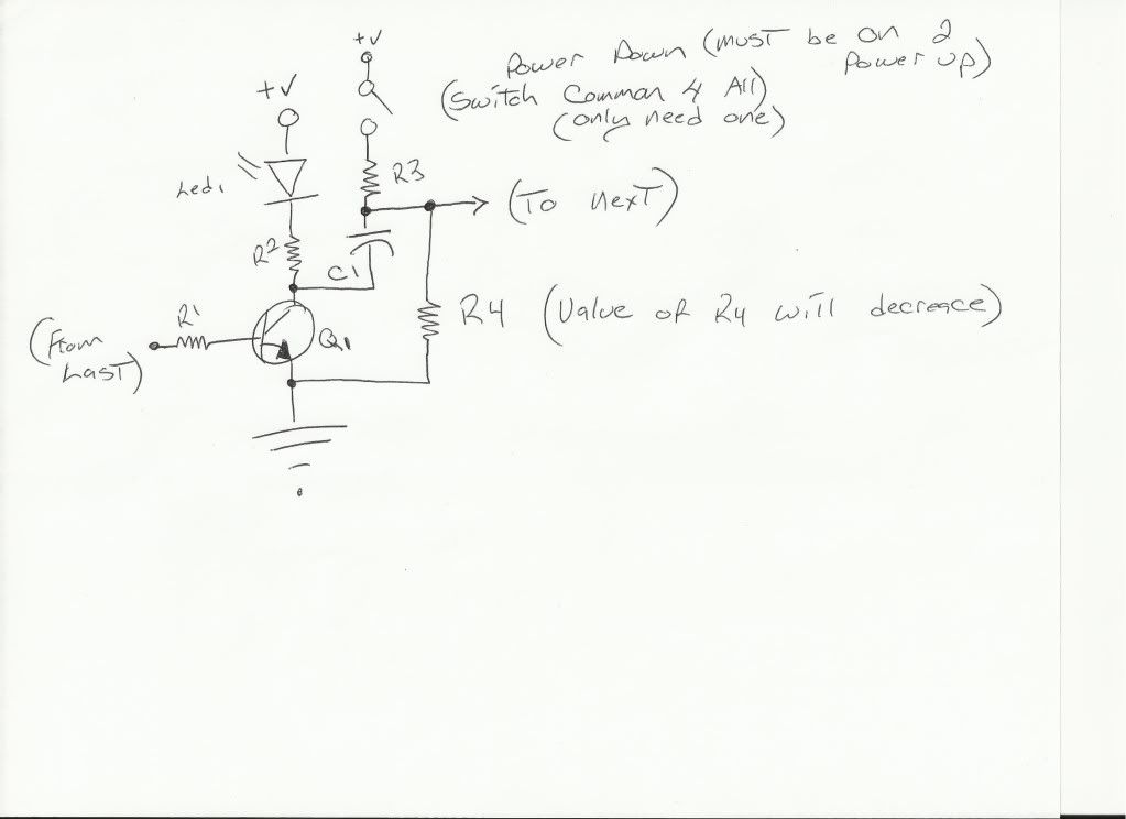
well, if you wanted to take a different route, you could build a non ic driving circuit to achieve the same thing with a multiple transister, capacitor and resistor circuit, such that when the cap on the prior led set is full, it turns on the next one. time is determined by mf value.
not sure off the top of my head how you would do the power down, but it shouldnt be that hard. Ill see if i can come up with a circuit for you. no microcontroller, but lots cheaper, simpler, though lots of soldering.
not sure off the top of my head how you would do the power down, but it shouldnt be that hard. Ill see if i can come up with a circuit for you. no microcontroller, but lots cheaper, simpler, though lots of soldering.
-
LightFantastic
- Posts: 3
- Joined: Sun Nov 28, 2010 10:42 am
circuit
something like this should work. would have to have one for each led or cluster of leds, and would have to calculate all the values, but wouldnt be hard at all. Should power up and down in sequence great.
http://i1177.photobucket.com/albums/x34 ... cuit-1.jpg
http://i1177.photobucket.com/albums/x34 ... cuit-1.jpg
Re: circuit
So it relies on different values for R4 to provide the sequential "power down"?LightFantastic wrote:something like this should work. would have to have one for each led or cluster of leds, and would have to calculate all the values, but wouldnt be hard at all. Should power up and down in sequence great.
http://i1177.photobucket.com/albums/x34 ... cuit-1.jpg
The problem with circuits like this is how they scale... 48 LEDs means 48 transistors, 192 resistors, 48 capacitors, etc... Meanwhile the whole job can be done with a single $4 microcontroller. :)
---GEC (三面図流の初段)
There are no rats.
The skulls eat them.
There are no rats.
The skulls eat them.
-
LightFantastic
- Posts: 3
- Joined: Sun Nov 28, 2010 10:42 am
-
Disillusionist
- Posts: 1134
- Joined: Wed Apr 09, 2003 10:11 pm
- Location: Closer than you think
Here's an option made by Tena Controls if you don't want to design, or build a circuit yourself. I've recently put one together myself for a demo unit, and it works verra nice!
http://www.laserfirecreations.com/Shields%20Up.html
http://www.laserfirecreations.com/Shields%20Up.html
Affordable laser cutting and engraving for the hobby community
www.laserfirecreations.com While you're at it, follow us on Facebook
www.laserfirecreations.com While you're at it, follow us on Facebook
Don't see a price...Disillusionist wrote:Here's an option made by Tena Controls if you don't want to design, or build a circuit yourself. I've recently put one together myself for a demo unit, and it works verra nice!
http://www.laserfirecreations.com/Shields%20Up.html
-
Disillusionist
- Posts: 1134
- Joined: Wed Apr 09, 2003 10:11 pm
- Location: Closer than you think
Whoops, sorry!...the word TenaControls just above the embedded YouTube video is a link to the TenaControls website. The price in on their page. 
Affordable laser cutting and engraving for the hobby community
www.laserfirecreations.com While you're at it, follow us on Facebook
www.laserfirecreations.com While you're at it, follow us on Facebook
-
Starshiner60
- Posts: 111
- Joined: Fri Feb 18, 2011 8:27 pm
- Location: Birmingham, Alabama
-
Starshiner60
- Posts: 111
- Joined: Fri Feb 18, 2011 8:27 pm
- Location: Birmingham, Alabama
I've just come across this thread, and coincidentally, I've just created one of these displays, also using an Arduino and a MAX7219 led matrix .
I was asked by a friend, who supplied me with one of Matt's (Laserfire Creations) display plaques, to see if I could come up with something. It works in much the same way as rabidpoobear's description, in that one switch controls the backlights in one position, the shields up or down sequence in another. A third position turns it off.
You can see my work in progress on my blog (see the sig below). I have it all running on a breadboard at the moment - thats why there is soooo much multi-coloured sphagetti in the background of the video there!
I've 99% finished the coding, and am about to make a pcb to mount the components on (the ATMega microprocessor from the Arduino gets a new home in a socket on the new pcb). The connections from the pcb to/from the plaque will be via ribbon cable.
It'll be powered from a 12V wall wart.
I'll keep you all informed of progress if you're interested.
WiredFX
Small Lighting and Effects UK
Small Lighting and Effects UK
Gettin' there. Got the pcb etched, just down to soldering the components on and check it all still works!
By the way, if anyone else intends laser printing pcb designs onto a transfer medium, don't use a Brother laser printer - it don't work! I think they must use some form of different toner to HP, Xerox and the rest as it won't do the transfer to the copper. Errr, anyone interested in a second hand Brother printer 
By the way, if anyone else intends laser printing pcb designs onto a transfer medium, don't use a Brother laser printer - it don't work! I think they must use some form of different toner to HP, Xerox and the rest as it won't do the transfer to the copper. Errr, anyone interested in a second hand Brother printer
WiredFX
Small Lighting and Effects UK
Small Lighting and Effects UK