Electronic Circuits Help
Moderators: Sparky, Moderators
-
Sparky
- Moderator
- Posts: 2404
- Joined: Thu Jun 05, 2003 8:28 am
- Location: Are we there yet? (Chicago)
- Contact:
Electronic Circuits Help
Here's a sticky for electronic circuits and dodads.
<a href="http://www.kc6sye.com/2_wheresaneatpart.jpg" target="_Sparky">Is this plastic thingy on the counter a neat part?</a> <a href="http://www.kc6sye.com/1_casting_inprogress.jpg" target="_Sparky">Let's cast it.</a>
-
Sparky
- Moderator
- Posts: 2404
- Joined: Thu Jun 05, 2003 8:28 am
- Location: Are we there yet? (Chicago)
- Contact:
Here are Zog's LED circuits:
The counter with external clock (Johnson counter):
http://www.kc6sye.com/images/circuits/4 ... pdated.jpg
The original counter with external clock (to see what Zog updated):
http://www.kc6sye.com/images/circuits/4017_diagram.jpg
The Basic binary Counter with onboard clock:
http://www.kc6sye.com/images/circuits/4060_basic.jpg
Please note, if you look closely to the cap, it connects across pin 9 and 11, not 9 (out2) and 10 (out1). Thanks to Sam, for pointing out that the eye can trick you, even I made the mistake. i'll try to clean up the pic to remove the chance mistake.
Last edited by Sparky on Fri Oct 12, 2007 12:16 am, edited 4 times in total.
<a href="http://www.kc6sye.com/2_wheresaneatpart.jpg" target="_Sparky">Is this plastic thingy on the counter a neat part?</a> <a href="http://www.kc6sye.com/1_casting_inprogress.jpg" target="_Sparky">Let's cast it.</a>
-
en'til Zog
- Posts: 2405
- Joined: Fri Jul 12, 2002 3:03 pm
- Location: The Wilds of Northwoods Wisconsin
-
Sparky
- Moderator
- Posts: 2404
- Joined: Thu Jun 05, 2003 8:28 am
- Location: Are we there yet? (Chicago)
- Contact:
Forgot about these simple pulse lighting circuits from zog, they answer this question:
Is there a nice cheap n' easy way to have a fade effect on a circuit? I would think it could be done with capacitors. . .
<A HREF="http://www.kc6sye.com/images/circuits/s ... _blink.jpg" target="_blank">Slow Pulsating Blink</A>
<A HREF="http://www.kc6sye.com/images/circuits/s ... _wtran.jpg" target="_blank">slow Pulsating Blink usin' a transistor</A>
Last edited by Sparky on Sun Aug 17, 2008 4:04 am, edited 1 time in total.
<a href="http://www.kc6sye.com/2_wheresaneatpart.jpg" target="_Sparky">Is this plastic thingy on the counter a neat part?</a> <a href="http://www.kc6sye.com/1_casting_inprogress.jpg" target="_Sparky">Let's cast it.</a>
-
Sparky
- Moderator
- Posts: 2404
- Joined: Thu Jun 05, 2003 8:28 am
- Location: Are we there yet? (Chicago)
- Contact:
By popular demand, here's the link to the 'gentle throbbing' LED circuit, AKA the triangle wave generator.
There's a good reference for a 'gentle pulsing' circuit from some computer moders in the UK, let me find the link. . .
http://www.cpemma.co.uk/throbber.html
new link
http://www.pcsilencioso.com/cpemma/throbber.html
Please let me know if this link dies, and I created a circuit diagram in Eagle as a back up.
Last edited by Sparky on Mon Feb 07, 2011 7:58 pm, edited 3 times in total.
<a href="http://www.kc6sye.com/2_wheresaneatpart.jpg" target="_Sparky">Is this plastic thingy on the counter a neat part?</a> <a href="http://www.kc6sye.com/1_casting_inprogress.jpg" target="_Sparky">Let's cast it.</a>
-
Sparky
- Moderator
- Posts: 2404
- Joined: Thu Jun 05, 2003 8:28 am
- Location: Are we there yet? (Chicago)
- Contact:
Some more circuit ideas from Zog.
Some simple LED drivers, and help with transistor boosting for more LED driving power.
<A HREF="http://www.kc6sye.com/images/circuits/t ... s_CMOS.jpg" target="_blank">Transistor Drivers and CMOS</A>
And some simple blink circuits and then one with a hook up that produces a simulated arc & spark output, weld on little mech diorama guys!
<A HREF="http://www.kc6sye.com/images/circuits/4 ... w_tooo.jpg" target="_blank">4060 How Too</A>
<A HREF="http://www.kc6sye.com/images/circuits/4 ... how_to.jpg" target="_blank">4060 Heart sizzle How To</A>
<a href="http://www.kc6sye.com/2_wheresaneatpart.jpg" target="_Sparky">Is this plastic thingy on the counter a neat part?</a> <a href="http://www.kc6sye.com/1_casting_inprogress.jpg" target="_Sparky">Let's cast it.</a>

4060 How Too question
Just getting into lighting my kits. Now I guess I am not understanding what I am reading, but am I to understand that this 4060 configuration will some how simulate a sparking effect? I don't understand what is causing the effect? A rapidly flashing led? A real spark between wires?
-
Sparky
- Moderator
- Posts: 2404
- Joined: Thu Jun 05, 2003 8:28 am
- Location: Are we there yet? (Chicago)
- Contact:
The idea is to build a circuit that will bilnk an LED with a random flash. I think this circuit allows noise to trip the threshold of the circuit so that the LED randomally flashes.
<a href="http://www.kc6sye.com/2_wheresaneatpart.jpg" target="_Sparky">Is this plastic thingy on the counter a neat part?</a> <a href="http://www.kc6sye.com/1_casting_inprogress.jpg" target="_Sparky">Let's cast it.</a>
This is a great intro, however for someone that has zero knowledge of electrical circuitry there's still a lot of jargon in the how to section that only someone familiar circuits would know.
Example:
Bread board
Parts conductor
Resistor
Some basic definitions would be really helpful along with some pictures.
The circuit diagrams would be much more helpful to a beginner of there was a real example to look at sitting next to it.
My 2 cents.
Example:
Bread board
Parts conductor
Resistor
Some basic definitions would be really helpful along with some pictures.
The circuit diagrams would be much more helpful to a beginner of there was a real example to look at sitting next to it.
My 2 cents.
-
Sparky
- Moderator
- Posts: 2404
- Joined: Thu Jun 05, 2003 8:28 am
- Location: Are we there yet? (Chicago)
- Contact:
If we setup such a pirmer it would probably be hosted on the main site, there are two or three on working with LEDs.
Most of the basics though can be found on the web and are written by guys who have been teaching electronics basics to new HAMs for more years than I have.
And looking at a hand wired circuit would be enough to scare off many newbis.
Here's a bread board with about 4 working circuits in some phase of testing.
http://www.kc6sye.com/images/images_01_ ... C01163.jpg
On that note, I think we can start creating an electronics basics tutorial. Again though it will be in the Ask Nigel section of the main site. Things we like to keep here are the speciallty circuits we have tried out and know look good.
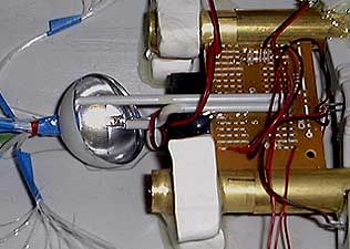
I have a random arc welding circuit I need to add here for reference. It looks really good when you look at the light cast by the LED. Looking right at the LED makes it hard to see the effect. The eye gets saturated by the LEd and you cant see the subtle flickering that is going on.
Most of the basics though can be found on the web and are written by guys who have been teaching electronics basics to new HAMs for more years than I have.
And looking at a hand wired circuit would be enough to scare off many newbis.
Here's a bread board with about 4 working circuits in some phase of testing.
http://www.kc6sye.com/images/images_01_ ... C01163.jpg
On that note, I think we can start creating an electronics basics tutorial. Again though it will be in the Ask Nigel section of the main site. Things we like to keep here are the speciallty circuits we have tried out and know look good.
I have a random arc welding circuit I need to add here for reference. It looks really good when you look at the light cast by the LED. Looking right at the LED makes it hard to see the effect. The eye gets saturated by the LEd and you cant see the subtle flickering that is going on.
<a href="http://www.kc6sye.com/2_wheresaneatpart.jpg" target="_Sparky">Is this plastic thingy on the counter a neat part?</a> <a href="http://www.kc6sye.com/1_casting_inprogress.jpg" target="_Sparky">Let's cast it.</a>
-
Sparky
- Moderator
- Posts: 2404
- Joined: Thu Jun 05, 2003 8:28 am
- Location: Are we there yet? (Chicago)
- Contact:
Here are Zog's Bread Board useage and operation diagram:
http://www.kc6sye.com/images/circuits/Bread_board.jpg
http://www.kc6sye.com/images/circuits/Bread_board.jpg
<a href="http://www.kc6sye.com/2_wheresaneatpart.jpg" target="_Sparky">Is this plastic thingy on the counter a neat part?</a> <a href="http://www.kc6sye.com/1_casting_inprogress.jpg" target="_Sparky">Let's cast it.</a>
-
Sparky
- Moderator
- Posts: 2404
- Joined: Thu Jun 05, 2003 8:28 am
- Location: Are we there yet? (Chicago)
- Contact:
General Soldering tips:
A good fact sheet is up over here under solder tips:
http://www.n0ss.net/index_general.html
Its in PDf so you can download it for offline access and print it or keep it up on the screen whichever is easies.
A good fact sheet is up over here under solder tips:
http://www.n0ss.net/index_general.html
Its in PDf so you can download it for offline access and print it or keep it up on the screen whichever is easies.
<a href="http://www.kc6sye.com/2_wheresaneatpart.jpg" target="_Sparky">Is this plastic thingy on the counter a neat part?</a> <a href="http://www.kc6sye.com/1_casting_inprogress.jpg" target="_Sparky">Let's cast it.</a>
-
Sparky
- Moderator
- Posts: 2404
- Joined: Thu Jun 05, 2003 8:28 am
- Location: Are we there yet? (Chicago)
- Contact:
From zog some notes on fusion core:
For the JII:
http://www.kc6sye.com/images/circuits/4 ... r_core.jpg
For the C57-D:
http://www.kc6sye.com/images/circuits/4 ... r_core.jpg
For the JII:
http://www.kc6sye.com/images/circuits/4 ... r_core.jpg
For the C57-D:
http://www.kc6sye.com/images/circuits/4 ... r_core.jpg
<a href="http://www.kc6sye.com/2_wheresaneatpart.jpg" target="_Sparky">Is this plastic thingy on the counter a neat part?</a> <a href="http://www.kc6sye.com/1_casting_inprogress.jpg" target="_Sparky">Let's cast it.</a>
-
Sparky
- Moderator
- Posts: 2404
- Joined: Thu Jun 05, 2003 8:28 am
- Location: Are we there yet? (Chicago)
- Contact:
here's a link to some trek lighting circuits from virtualight:
I'm updating my website to include all the different things at which I'm incompetent, and I decided to make a little tutorial on how I built the board for my PL TOS Enterprise.
The website is still being built so very little works except the tutorial. Click the link that says electronics schematics in the left colum.
http://www.virtualight.com/
Thanks,
Jennifer
<a href="http://www.kc6sye.com/2_wheresaneatpart.jpg" target="_Sparky">Is this plastic thingy on the counter a neat part?</a> <a href="http://www.kc6sye.com/1_casting_inprogress.jpg" target="_Sparky">Let's cast it.</a>
-
en'til Zog
- Posts: 2405
- Joined: Fri Jul 12, 2002 3:03 pm
- Location: The Wilds of Northwoods Wisconsin
The Jupiter II lighting circuit above is for the Movie version which has a 30 panel "fusion core" rather than the 32 panel one for TOS version. I'll work on that one, but the circuit for the C57-D can be modified using the 4017 outputs 0 to 7, 8 goes to reset, and you use 4 LEDs per output - using LEDs that need 2 volts or less.
HTH
HTH
-
MillenniumFalsehood

- Posts: 16998
- Joined: Tue Nov 16, 2004 5:23 pm
- Location: Wichita, KS, USA
- Contact:
Is there a way to put a blinking LED in a circuit without causing a significant or noticeable drop in voltage across the board, short of using two power sources?
If a redhead works at a bakery, does that make him a gingerbread man?
Ponies defeat a Star Trek villain? Give them a Star Wars award ceremony!
Ponies defeat a Star Trek villain? Give them a Star Wars award ceremony!

You shouldn't be seeing a reduction in voltage unless you're overtaxing your power supply... Put the blinking LED, with current-limiting resistor, in parallel with the rest of your circuit and it should be fine.MillenniumFalsehood wrote:Is there a way to put a blinking LED in a circuit without causing a significant or noticeable drop in voltage across the board, short of using two power sources?
---GEC (三面図流の初段)
There are no rats.
The skulls eat them.
There are no rats.
The skulls eat them.
-
MillenniumFalsehood
- Posts: 16998
- Joined: Tue Nov 16, 2004 5:23 pm
- Location: Wichita, KS, USA
- Contact:
Okay, thanks. That worked like a charm. 
If a redhead works at a bakery, does that make him a gingerbread man?
Ponies defeat a Star Trek villain? Give them a Star Wars award ceremony!
Ponies defeat a Star Trek villain? Give them a Star Wars award ceremony!
-
Sparky
- Moderator
- Posts: 2404
- Joined: Thu Jun 05, 2003 8:28 am
- Location: Are we there yet? (Chicago)
- Contact:
Something new form Zog:
http://www.kc6sye.com/images/circuits/4 ... gram_L.jpg
This is good for those that are setting up computer banks or cockpits with a lot of lights and buttons
http://www.kc6sye.com/images/circuits/4 ... gram_L.jpg
a bit odd. Here's a way to multi-clock a 4017 chip (counts from 0 - 9) with a 4060 chip (self clocking with 12 divide by 2 outputs). Why? the several outputs from the 4060 change at different rates making the scanning outputs of the 4017 sequentially blink at first a fast rate, then a slow one, maybe stopping for a bit. Looks very computery, like a computer is acquiring data (quick changes), then scanning data (slower more deliberate blinks) then pondering (pausing). Try different outputs from the 4060 to different inputs of the 4017, or two outputs from the 4060 and one negative ( - ) connection to the 4017 R input.
This is one case where the LEDs being driven by the 4017 should probably NOT be in a numerical 0 - 9 order, but scrambled so they appear to be blinking 'at random'.
This is good for those that are setting up computer banks or cockpits with a lot of lights and buttons
<a href="http://www.kc6sye.com/2_wheresaneatpart.jpg" target="_Sparky">Is this plastic thingy on the counter a neat part?</a> <a href="http://www.kc6sye.com/1_casting_inprogress.jpg" target="_Sparky">Let's cast it.</a>
-
Pat Amaral

- Posts: 3730
- Joined: Fri Jul 12, 2002 2:44 pm
- Location: Ok, I'm here. You can start now
-
Sparky
- Moderator
- Posts: 2404
- Joined: Thu Jun 05, 2003 8:28 am
- Location: Are we there yet? (Chicago)
- Contact:
The previous diagram has been updated to remove ambiguity.
Here's another one with more text descriptions:
http://www.kc6sye.com/images/circuits/4060_how_tooo.jpg
Here's the some text as well:
Here's another one with more text descriptions:
http://www.kc6sye.com/images/circuits/4060_how_tooo.jpg
Here's the some text as well:
Question?
Does it matter which of the three 4017 "In" inputs connects to the three 4060 outputs (4 and 7 and 10)?
Different combination of 4060 OUTPUTS to the three 4017 INPUTS will give different lighting effects. If things get too ‘odd’ just run NEGATIVE to the 4017 “ R “ INPUT (pinout # 15) but NOT any wire from the 4060, and experiment from there.
I'm still a little confusedicated about the 4060's Variable resistor--what its three pins connect to. You show it connects to "ck" and "out 1" in the diagram, (two connections). And the note also shows it connects to pin 11 and pin 10? (I don't see pin 11 in the diagram, because I'm a dummy). And pin 10 is one of the outputs going to the 4017 inputs right? Does pin 10 also connect to the VR?
The variable resistor has three wires coming out - the middle one connects to the ‘wiper’ inside the VR which moves along a stick of carbon (usually) inside the VR body which is what changes the resistance RELATIVE TO EACH END of the fixed resistance. The end pins connect to each end of the internal resistor.
Move the wiper one way, the resistance between it and one end goes UP and between it and the other end goes DOWN. So connect the 4060 to the middle pin and one end pin.
There’s two sets of numbers associated with the 4060 - the “pinout” numbers and the “What they Do” numbers.
The PINOUT numbers just number the pins sticking out of the little plastic block, with the TOP view, NOTCH to the LEFT, starting from the BOTTOM LEFT corner and pin - that’s PINOUT number ONE. Then you count COUNTERCLOCKWISE around to the right, then to the top row, still going COUNTERCLOCKWISE back to the left. On the 4060 NEGATIVE goes to pinout” 8 “ and “ 12 “, POSITIVE goes to pinout “ 16 “.
Now, there’s the “What They Do” numbers that have nothing to do with the physical location of the pins or pinouts. POSITIVE goes to the “ + “ pin and NEGATIVE goes to both the “ - “ and “ R “ “what they do” pins on the 4060.
On the 4017 there’s a “ 1/2 “ output - that just goes POSITIVE for half the 0-9 counts, and NEGATIVE for the other half. Like POS for 0-4 and NEG for 5-9. Or maybe the reverse.
<a href="http://www.kc6sye.com/2_wheresaneatpart.jpg" target="_Sparky">Is this plastic thingy on the counter a neat part?</a> <a href="http://www.kc6sye.com/1_casting_inprogress.jpg" target="_Sparky">Let's cast it.</a>
I'm not seeing anything about the most basic circuit layout, or any discussion of the fundamentals. Stuff like Ohm's Law, which a modeler can use to calculate the root-level requirements for lighting an LED, or simple circuit of LEDs, using any desired DC voltage.
A decent explanation and diagrams can be found at
http://www.techdose.com/electronics/Sim ... page1.html
But even there a fundamental aspect is left out.
The basic problem with lighting LEDs is matching the power supplied with the needs / operating limits of the chosen LEDs - or for that matter making the right choices in components in the first place, or understanding ahead of time which constraints you can pick and choose and which you are stuck with, so you can tailor your circuit design to cope with them.
LEDs have a desired voltage and amperage they'll operate. Different for different types of LEDs. Each discrete 'circuit' in your layout will need to accomodate this 'flavor' of power. So in addition to crafting your lighting solution by function (always on, some blinking, some separately controlled) you also have to group the components by power levels ('flavor', as I'm calling it).
Ohm's Law is the basic fomula for this, V=IR.
V=Voltage (voltage disparity, in terms of an LED lighting circuit)
I=Current(flow), typically expressed in whole Amps and in LED lighting, milliAmprs or mA. You'll find that rating on ea. LED you'll use.
R=Resistance, expressed in Ohms, the Omega symbol.
In laying out your desired lighting solution, you can effectively split your circuitry into separate parallel circuits, each running a different 'flavor', while keeping them all on the same power source, by using Ohm's law to calculate the different Resistor values needed to tone down the power feeding each lighting variety.
In this way you can size your power source for the peak power-hogging element in your lighting plan, and tamp it down for everything else.
This is just an option. You could use separate different-voltage power sources if you'd like. Or if internal space requirements drive different choices. This is also impacted by whether you want your lighting system totally contained within the model or will be incorporating the (usually bulky) power source or method into a display base or remotely located location.
Anyway, back to Ohm's Law, V=IR. The goal is figuring out what level of Resistor you need. For this explanation, I'm picking a 9V battey and a 'superbright' LED running at 3.2V and drawing 20mA of current.
To solve for V, you take the voltage of your power source and subtract the voltage rating of the LEDs (or other items) on your circuit. 9-3.2 in this case. 5.8V, which is how much excess voltage we have to get rid of / block / 'Resist'.
From the LED rating we know the desired current is 20mA. Recall that Ohm's Law uses whole Amps, so converting 20mA - milli, thousand - we get 0.02 Amps. Continuing to solve the equation, we divide 5.8V by 0.02A. For these purposes we ignore the V and A and it's a straight number crunch. The result is 290. Which in this equation is the Ohms value, 290 Ohms, which is the rating of the desired Resistor to tamp down our chosen power supply to light that single superbright LED.
Resistors come in a huge variety of ratings over an extremely wide range. But even so you aren't likely to find a perfect match. That's ok. Keep in mind that for the most part these devices have operating ranges. And keep in mind which end of the range you are working from, when picking your values for solving equations or sourcing components. In the above example I went with the low end of the voltage range for the LED. And the current figure is essentially a minimum. There's ~10% worth of wiggle room upward in the voltage rating, and likewise a similar bit of additional current that can be applied to the LED. If you use a little LOWER resistor rating you'll hit the LED with a bit MORE power. And vice versa.
Run the equation with both min and max voltage ratings to get an idea of the range of resistance you should emply, then pick whatever rating works. In general, the more towards the low end you stay, the longer the LEDs and your battery should last. A little low in the supplied power and you'll get a dim light. A good bit low and it'll fail to light at all. A little much, it might burn brighter. Too much, it might burn brighter for a very short amount of time.
I just pulled that out of the cobwebs of my mind, after digging up that web page. It's been several years since I crafted a circuit to light a model or prop, so I'm rusty. If I got something wrong I'm sure someone will correct me and I'll check back to edit this post.
And there are several other variables and options as well, depending on your lighting plan.
Multiple LEDs can be run on a single branch circuit, as long as their combined amperage is factored in.
There are differences in wiring LEDs in serial vs parallel fashion, likewise in the layouts of the circuits themselves.
With a little cleverness and luck, you can size your power supply sufficiently and run your LEDs in serial fashion and manage to light things without a resistor. But your lighting circuit is doomed if one of the LEDs burns out. Witing in parallel has far greater fault tolerance. Keep that in mind if you are lighting something you can't take apart.
There are also many other electronic components that can help you customize your circuit layouts, like all the timing and programmable chips discussed in these fixed topics.
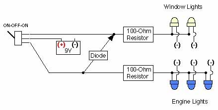
One basic element is a Diode, which acts as a sort of one-way gate for electricity. When I built my lighted Star Destroyer kit, I wanted the entire lighting packaged to be internal to the kit, and to be removeable / serviceable for a battery change or LED replacement. But I also wanted two (overlapping) functional circuits. One with all the fiber lit and one with fiber AND the engines lit. Using a single pole, double throw switch (ON-OFF-ON) and a diode, I was able to feed both options and control them with a single switch placement. Without the diode, the wire branching to feed both sets of lights would 'backfeed' and energize both circuits in both switch positions. Failure.
Anyway, without the diode it would have required two switches each with an isolated circuit to control things. And it was hard enough hiding one switch in plain sight on that small kit.
Here's a simple diagram of that circuit. The LEDs are wired in parallel.
http://img.photobucket.com/albums/v95/r ... iagram.jpg
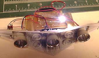
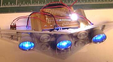
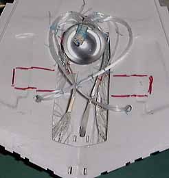
And here's a few of my solution. The engine backplane became the only readily removeable structure in my build. I used sleeved brass tubing as the retention and alignment method, with a bit of a friction fit doing the job. I laid out and bundled all the fiber into an upper and lower hull halves arrangement, with each half terminating in a bundle that I put thru a sectioned half of a ping pong ball, which I attempted to make a bit reflective, while coating it to block light seepage. I set up such a 'collector' in both the top and bottom halves. Then on the removeable engine / lighting module, I positioned a 'gang plank' of sorts to put the pair of fiber LEDs into position where they would shine on their respective bundles to best effect.
In this way my lit Star Destroyer could sit on a custom base supported by nothing but clear plex rods. No metal or blacked out tubing.
http://img.photobucket.com/albums/v95/r ... amera1.jpg
http://img.photobucket.com/albums/v95/r ... amera2.jpg
http://img.photobucket.com/albums/v95/r ... ytying.jpg
http://img.photobucket.com/albums/v95/r ... sition.jpg
http://img.photobucket.com/albums/v95/r ... ile400.jpg
A decent explanation and diagrams can be found at
http://www.techdose.com/electronics/Sim ... page1.html
But even there a fundamental aspect is left out.
The basic problem with lighting LEDs is matching the power supplied with the needs / operating limits of the chosen LEDs - or for that matter making the right choices in components in the first place, or understanding ahead of time which constraints you can pick and choose and which you are stuck with, so you can tailor your circuit design to cope with them.
LEDs have a desired voltage and amperage they'll operate. Different for different types of LEDs. Each discrete 'circuit' in your layout will need to accomodate this 'flavor' of power. So in addition to crafting your lighting solution by function (always on, some blinking, some separately controlled) you also have to group the components by power levels ('flavor', as I'm calling it).
Ohm's Law is the basic fomula for this, V=IR.
V=Voltage (voltage disparity, in terms of an LED lighting circuit)
I=Current(flow), typically expressed in whole Amps and in LED lighting, milliAmprs or mA. You'll find that rating on ea. LED you'll use.
R=Resistance, expressed in Ohms, the Omega symbol.
In laying out your desired lighting solution, you can effectively split your circuitry into separate parallel circuits, each running a different 'flavor', while keeping them all on the same power source, by using Ohm's law to calculate the different Resistor values needed to tone down the power feeding each lighting variety.
In this way you can size your power source for the peak power-hogging element in your lighting plan, and tamp it down for everything else.
This is just an option. You could use separate different-voltage power sources if you'd like. Or if internal space requirements drive different choices. This is also impacted by whether you want your lighting system totally contained within the model or will be incorporating the (usually bulky) power source or method into a display base or remotely located location.
Anyway, back to Ohm's Law, V=IR. The goal is figuring out what level of Resistor you need. For this explanation, I'm picking a 9V battey and a 'superbright' LED running at 3.2V and drawing 20mA of current.
To solve for V, you take the voltage of your power source and subtract the voltage rating of the LEDs (or other items) on your circuit. 9-3.2 in this case. 5.8V, which is how much excess voltage we have to get rid of / block / 'Resist'.
From the LED rating we know the desired current is 20mA. Recall that Ohm's Law uses whole Amps, so converting 20mA - milli, thousand - we get 0.02 Amps. Continuing to solve the equation, we divide 5.8V by 0.02A. For these purposes we ignore the V and A and it's a straight number crunch. The result is 290. Which in this equation is the Ohms value, 290 Ohms, which is the rating of the desired Resistor to tamp down our chosen power supply to light that single superbright LED.
Resistors come in a huge variety of ratings over an extremely wide range. But even so you aren't likely to find a perfect match. That's ok. Keep in mind that for the most part these devices have operating ranges. And keep in mind which end of the range you are working from, when picking your values for solving equations or sourcing components. In the above example I went with the low end of the voltage range for the LED. And the current figure is essentially a minimum. There's ~10% worth of wiggle room upward in the voltage rating, and likewise a similar bit of additional current that can be applied to the LED. If you use a little LOWER resistor rating you'll hit the LED with a bit MORE power. And vice versa.
Run the equation with both min and max voltage ratings to get an idea of the range of resistance you should emply, then pick whatever rating works. In general, the more towards the low end you stay, the longer the LEDs and your battery should last. A little low in the supplied power and you'll get a dim light. A good bit low and it'll fail to light at all. A little much, it might burn brighter. Too much, it might burn brighter for a very short amount of time.
I just pulled that out of the cobwebs of my mind, after digging up that web page. It's been several years since I crafted a circuit to light a model or prop, so I'm rusty. If I got something wrong I'm sure someone will correct me and I'll check back to edit this post.
And there are several other variables and options as well, depending on your lighting plan.
Multiple LEDs can be run on a single branch circuit, as long as their combined amperage is factored in.
There are differences in wiring LEDs in serial vs parallel fashion, likewise in the layouts of the circuits themselves.
With a little cleverness and luck, you can size your power supply sufficiently and run your LEDs in serial fashion and manage to light things without a resistor. But your lighting circuit is doomed if one of the LEDs burns out. Witing in parallel has far greater fault tolerance. Keep that in mind if you are lighting something you can't take apart.
There are also many other electronic components that can help you customize your circuit layouts, like all the timing and programmable chips discussed in these fixed topics.
One basic element is a Diode, which acts as a sort of one-way gate for electricity. When I built my lighted Star Destroyer kit, I wanted the entire lighting packaged to be internal to the kit, and to be removeable / serviceable for a battery change or LED replacement. But I also wanted two (overlapping) functional circuits. One with all the fiber lit and one with fiber AND the engines lit. Using a single pole, double throw switch (ON-OFF-ON) and a diode, I was able to feed both options and control them with a single switch placement. Without the diode, the wire branching to feed both sets of lights would 'backfeed' and energize both circuits in both switch positions. Failure.
Anyway, without the diode it would have required two switches each with an isolated circuit to control things. And it was hard enough hiding one switch in plain sight on that small kit.
Here's a simple diagram of that circuit. The LEDs are wired in parallel.
http://img.photobucket.com/albums/v95/r ... iagram.jpg
And here's a few of my solution. The engine backplane became the only readily removeable structure in my build. I used sleeved brass tubing as the retention and alignment method, with a bit of a friction fit doing the job. I laid out and bundled all the fiber into an upper and lower hull halves arrangement, with each half terminating in a bundle that I put thru a sectioned half of a ping pong ball, which I attempted to make a bit reflective, while coating it to block light seepage. I set up such a 'collector' in both the top and bottom halves. Then on the removeable engine / lighting module, I positioned a 'gang plank' of sorts to put the pair of fiber LEDs into position where they would shine on their respective bundles to best effect.
In this way my lit Star Destroyer could sit on a custom base supported by nothing but clear plex rods. No metal or blacked out tubing.
http://img.photobucket.com/albums/v95/r ... amera1.jpg
http://img.photobucket.com/albums/v95/r ... amera2.jpg
http://img.photobucket.com/albums/v95/r ... ytying.jpg
http://img.photobucket.com/albums/v95/r ... sition.jpg
http://img.photobucket.com/albums/v95/r ... ile400.jpg
Signature Intentionally Left Blank
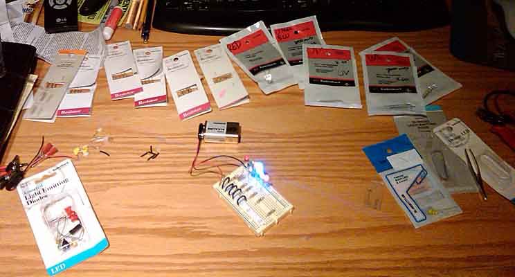
earlier today I picked up a few components, working on some lighting projects myself.
I tidied up my old LED related stuff to see what I was missing, vs what I wanted to try. I also dug out my breadboard.
So this evening I set about testing some loose LEDs to ID them, so I set up a sort of scale tester. I spaced out all variety of resistors I had, lowest rated value to highest, and energized the board. Then I worked my way thru the highest resister to lowest, watching to see where the unknown LEDs first got the brightest. Then from that figuring a rough voltage estimation on the LEDs.
http://img.photobucket.com/albums/v95/r ... EDohm1.jpg
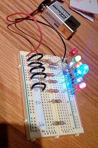
Once I was done with that I plugged in a variety of known LEDs just for show. All the disparate resistor circuits are essentially in parallel. And the few that have multiple LEDs running off them, the LEDs are also in parallel on that individual resistor. All running off a single 9V.
http://img.photobucket.com/albums/v95/r ... EDohm2.jpg
A breadboard is a handy thing to have, or at least get a dozen or so tiny alligator clips. That way you can at least clamp the various components together to test drive your configurations and the components in them.
It's also a handy trick to cull an LEDs or small connector plugs from any old computer equipment you're discarding. The bits come in handy sometimes.
I tidied up my old LED related stuff to see what I was missing, vs what I wanted to try. I also dug out my breadboard.
So this evening I set about testing some loose LEDs to ID them, so I set up a sort of scale tester. I spaced out all variety of resistors I had, lowest rated value to highest, and energized the board. Then I worked my way thru the highest resister to lowest, watching to see where the unknown LEDs first got the brightest. Then from that figuring a rough voltage estimation on the LEDs.
http://img.photobucket.com/albums/v95/r ... EDohm1.jpg
Once I was done with that I plugged in a variety of known LEDs just for show. All the disparate resistor circuits are essentially in parallel. And the few that have multiple LEDs running off them, the LEDs are also in parallel on that individual resistor. All running off a single 9V.
http://img.photobucket.com/albums/v95/r ... EDohm2.jpg
A breadboard is a handy thing to have, or at least get a dozen or so tiny alligator clips. That way you can at least clamp the various components together to test drive your configurations and the components in them.
It's also a handy trick to cull an LEDs or small connector plugs from any old computer equipment you're discarding. The bits come in handy sometimes.
Signature Intentionally Left Blank
-
severedblue
- Posts: 30
- Joined: Tue Dec 28, 2010 8:52 pm
- Location: Melbourne, Australia
Going through all of Zog's circuits on my breadboard here, most excellent.Sparky wrote:Some more circuit ideas from Zog.
Some simple LED drivers, and help with transistor boosting for more LED driving power.
<A HREF="http://www.kc6sye.com/images/circuits/t ... s_CMOS.jpg" target="_blank">Transistor Drivers and CMOS</A>
Does anyone have any idea on what values for the resistor / capacitor in the 4011 NAND configurations in this diagram? I take it the values are similar to what is needed to get the 4060 going....
-
severedblue
- Posts: 30
- Joined: Tue Dec 28, 2010 8:52 pm
- Location: Melbourne, Australia
Update on this, I couldn't get it (the top left design, 4011B NAND as a low power blinkie) working,severedblue wrote:Going through all of Zog's circuits on my breadboard here, most excellent.Sparky wrote:Some more circuit ideas from Zog.
Some simple LED drivers, and help with transistor boosting for more LED driving power.
<A HREF="http://www.kc6sye.com/images/circuits/t ... s_CMOS.jpg" target="_blank">Transistor Drivers and CMOS</A>
Does anyone have any idea on what values for the resistor / capacitor in the 4011 NAND configurations in this diagram? I take it the values are similar to what is needed to get the 4060 going....
I tried a 1uF aluminium electrolytic cap , as well as a .1uF ceramic cap, but couldn't get it to light
I used a variable resistor through the full wiper range
Finally, I checked my NAND gate was working against the 4060 set up, which it was. Without the values of the resistor and capacitor, it'll be difficult to proceed further (I understand RC calculations, but am not entirely sure of the purpose of the design so cannot do an educated guess of the resistor values)
I am definitely using a 9V supply
I'm not asking for help here, just leaving this note should anyone else attempt that design. I'm dismantling that design from my breadboard now.
-
Sparky
- Moderator
- Posts: 2404
- Joined: Thu Jun 05, 2003 8:28 am
- Location: Are we there yet? (Chicago)
- Contact:
in addition to ohm's law:
E=I*R
(also sometimes written as V=I*R)
don't forget
PIE
P = I*E
E is electromotive force and is measured in Volts
P is power and is measure in Watts
I is current and is measured in Amps
R is resistance and is measured in Ohms
The rest of Direct Current (DC) ohm's laws has to do with the next steps in circuits.
Like parallel loops and series loops.
The basics are this:
Voltage across parallel loops is equal, current is additive (can be different for each loop though)
Voltage in series loops is cumulative (can be different for each element), but current is constant.
<a href="http://www.kc6sye.com/2_wheresaneatpart.jpg" target="_Sparky">Is this plastic thingy on the counter a neat part?</a> <a href="http://www.kc6sye.com/1_casting_inprogress.jpg" target="_Sparky">Let's cast it.</a>
Here is a navigation lights, strobe lights, rotation effect circuit for an Enterprise model
http://dl.dropbox.com/u/33437675/enterprisediagram.pdf
http://dl.dropbox.com/u/33437675/enterprisediagram.pdf