Problems with 4060 chips...

Ask and answer questions, share tips and resources for installing lighting and other electronics in your models.

Moderators: Sparky, Moderators

Post Reply
User avatar
Darkowski
Posts: 170
Joined: Tue Aug 19, 2008 7:13 pm
Location: Montreal

Problems with 4060 chips...

Post by Darkowski »

I'm in the process of building my first lit model - Deep Space 9.
As I'm new to lighting models, I was following the instructions from this link:
http://www.starshipmodeler.com/tech/cj_blink.htm.

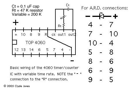
I bought 5 4060 chips and several capacitors and resistors as mentioned on that page.
After making the first circuit and playing with it, it didn't seem to work properly. My 'test' led was blinking randomly, without any regular pattern, or was just continuously lit, or wasn't lit at all...
So I checked each chip, every time using a new capacitor and resistor.
And after checking all 5 chips, I came to the conclusion that only one chip 4060 worked. Is that possible? I know these chips are static sensitive but still... could 4 out of 5 recently purchased chips be defective?

Should I buy the 555 chip instead? :?
jwrjr

Post by jwrjr »

555s are controllable. It depends on exactly what you want to do.
User avatar
Darkowski
Posts: 170
Joined: Tue Aug 19, 2008 7:13 pm
Location: Montreal

Post by Darkowski »

Controllable?

I just want approximately 4 leds flashing like on the 3 defensive sails in the DS9 series.

I'm planning to use one flashing red led to power up the fiber optics in the sails, and 3 other leds to flash on the upper docking pylons.

Thanks for you help!
jwrjr

Post by jwrjr »

If you pick the 2 resistors and the timing capacitor well, you can do quite a bit with a 555.
User avatar
Darkowski
Posts: 170
Joined: Tue Aug 19, 2008 7:13 pm
Location: Montreal

Post by Darkowski »

jwrjr wrote:If you pick the 2 resistors and the timing capacitor well, you can do quite a bit with a 555.
Ok, but I have no idea how to use a 555, so I have no idea what "the" 2 capacitors you're talking about, nor what pin to connect them to... :oops:

Are there any simple schematics on the web about the 555 like the 4060?
I found a few but they are a little too complicated for someone that never studied electronics....
jwrjr

Post by jwrjr »

I used the schematics that come in the datesheets. To get those download them from the website of anybody who makes the chip. It is often enough used that there probably websites with such info. But I don't know where they are.
en'til Zog
Posts: 2405
Joined: Fri Jul 12, 2002 3:03 pm
Location: The Wilds of Northwoods Wisconsin

Post by en'til Zog »

Hi, Darkowski.

Just a couple 'a things.

My wiring diagrams use these conventions.

TOP view of the chips, pins pointing DOWN like they’re stuck into a solderless or experimenter’s breadboard. The notch on the chip is to the LEFT. That puts the POSITIVE connection to the top left on the illustration, and the NEGATIVE to the bottom right. Pins are numbered COUNTERCLOCKWISE from the bottom left, around to the bottom right (1 - 8 for the 4060) and from the top right back to the top left ( 9-16 for the 4060).

On the 4060 the timing resistor goes between 10 and 11, the cap between 9 and 11. NEGATIVE power goes to pin 8, POSITIVE to pin 16.

You MUST connect pin 12 (R or RESET) to NEGATIVE to make everything clock.

4060 chips are pretty reliable. Just try again, with a cheap solderless breadboard preferably. Those are $4 US from ALL or Electronic Goldmine.

PM me with your eeeemail addy, and I can send you a NEW! shinney version of the wiring diagram.
User avatar
Darkowski
Posts: 170
Joined: Tue Aug 19, 2008 7:13 pm
Location: Montreal

Post by Darkowski »

Zog, don't get me wrong, I understand your diagram and I thank you for it :)
Like I said, one chip works fine, but the other 4 seem to be defective... maybe I didn't solder the components well... or the components could be defective?

I'll play more with the circuit tomorrow. If I run into more problems, I'll pm you for sure! :wink:

Danke!
en'til Zog
Posts: 2405
Joined: Fri Jul 12, 2002 3:03 pm
Location: The Wilds of Northwoods Wisconsin

Post by en'til Zog »

Cool! :D
User avatar
DLMatthys
Posts: 2707
Joined: Fri Jul 12, 2002 9:45 pm
Location: "Fracking? Not in my back yard. Now get off my ranch!
Contact:

Post by DLMatthys »

I have not played around to much with the 4060 chip but I do know and recommend a IC chip socket on your board rather than soldering the chip direct onto the board. You can then lift and remove the chip from the circuit.

I have read also to take precautions for this chip about avoiding static electricity and excessive heat when soldur is applied.

I got several of the chips in my bin stash of parts...I want to try it on this circuit than can give me a double blink...Good for modern aircraft:

http://www.cpemma.co.uk/blink.html
DL Matthys
don@dlmparts.com
http://www.dlmparts.com
Make it Glow!
en'til Zog
Posts: 2405
Joined: Fri Jul 12, 2002 3:03 pm
Location: The Wilds of Northwoods Wisconsin

Post by en'til Zog »

The multiple strobing effect is what I used in my CPD Power Armor suit, using the 4060 - that's 4 LEDs, two at a time. Plus the 'eye' LED.

I looked at the UK site you mentioned DL, and find a few things I disagree with. Like "The 4060B can only supply a few mA, just enough to light a single LED." BULL hockey. Look at my ARD schematic - one 4060, lighting 7 LEDs - brightly. Well, bright enough for all practical purposes - you get about 10 to 11 mA of current from each 4060 output which lights a high performance LED just fine.

http://www.starshipmodeler.com/other/cj_ARDcircuit.jpg gives the A.R.D. schmatic, and http://www.starshipmodeler.com/other/cj_ard.htm gives the rest of the article.

I've made a Nu-Trek tricorder from one of the toys, with a 5 x 7 Bi-color LED matrix, and other LEDs all running at once driven by 3@ 4060's giving literally half a billion combinations, all LEDs nicely visible.

The 4060 can do a LOT more than flashing one LED! :D
Last edited by en'til Zog on Fri Sep 05, 2008 12:08 am, edited 1 time in total.
Sparky
Moderator
Posts: 2404
Joined: Thu Jun 05, 2003 8:28 am
Location: Are we there yet? (Chicago)
Contact:

Post by Sparky »

Please note that some soldering irons will blow out a cmos chip very quickly, they have transient voltages on the tip or aren't static protected. They worked fine for older chips but the newer cmos chips are more sensitive.

Had a project that used a flip flop to de-bounce a regular push button, problem was every time we put in a new chip it would work once or twice then 'lock up.' The older temperature controlled soldering iron was damaging the internal connections of the chip when it would click back on as the heat control activated (during the soldering process). Took us a long time to trace out that problem.
<a href="http://www.kc6sye.com/2_wheresaneatpart.jpg" target="_Sparky">Is this plastic thingy on the counter a neat part?</a> <a href="http://www.kc6sye.com/1_casting_inprogress.jpg" target="_Sparky">Let's cast it.</a>
en'til Zog
Posts: 2405
Joined: Fri Jul 12, 2002 3:03 pm
Location: The Wilds of Northwoods Wisconsin

Post by en'til Zog »

AH HA! Killer soldering irons! I'm very glad I haven't run into that problem! I'd say using a socket would definitely save that situation. Thanks Don & Sparky for more information.
User avatar
Darkowski
Posts: 170
Joined: Tue Aug 19, 2008 7:13 pm
Location: Montreal

Post by Darkowski »

Well, I went to buy 5 more 4060 chips today (thinking that maybe I burnt the other 5 while soldering), along with the sockets in case I would use the soldering iron again. :P

First, I didn't want to solder them, so I tested each new chip on a solderless breadboard and making that circuit one more time. And still... same problem... depending what pins I'm touching, the led just lights up or doesn't light up at all :evil:
One led even burnt!

I even changed the capacitor and resistor to see if that would solve the problem, with no luck.
I'll try to make a circuit tomorrow by soldering the components, without the use of a board.

I'm starting to think that all the chips the store sold me are bad...
It's a store called Addison Electronics here in Canada.
I think I'll try to buy a few from Jameco like Zog said... The thing is... I found different 4060 chips.... not sure which one to choose...
Any help would be appreciated :oops:

Darek
Sparky
Moderator
Posts: 2404
Joined: Thu Jun 05, 2003 8:28 am
Location: Are we there yet? (Chicago)
Contact:

Post by Sparky »

IT sounds like you might be running the chip with more power than it needs. Most of the chips have a larger operating voltage, but LEDs don't. If you are running the chip at 3 or 4 volts you should be ok.

I don't see how you could have burned out an LED, unless you were dropping a lot of voltage across it.

Is all the grounds on your setup grounded, check for static build up on your person and on equipment. If you are using a 3 prong to 2 prong adapter make sure it is captured by the screw terminal on the plate cover and that the screw terminal has a connection to ground. measure AC volts from the hot side of the outlet to the ground and it should read ~120 volts ac.
<a href="http://www.kc6sye.com/2_wheresaneatpart.jpg" target="_Sparky">Is this plastic thingy on the counter a neat part?</a> <a href="http://www.kc6sye.com/1_casting_inprogress.jpg" target="_Sparky">Let's cast it.</a>
User avatar
Pat Amaral
Posts: 3730
Joined: Fri Jul 12, 2002 2:44 pm
Location: Ok, I'm here. You can start now

Post by Pat Amaral »

Last night, I breadboarded the last circuit on this page and it worked as designed (I'm running the circuit at 9v from a benchtop power supply). The only difference is I replaced Rt with a 500k potentiometer so I could play with the speed. I also hung a green LED on the 8/9 outputs like Zog mentioned. The only time I experienced goofy operation like Darkowski described was when I adjusted the pot to its extremes. My only suggestions are to check (once again) your component values (specifically Rt and Ct) and all of your connections.
Pat A.
=============================
50% Nerd, 50% Geek, 100% Cool
Scott Hasty
Posts: 3419
Joined: Fri Jul 12, 2002 4:13 pm
Location: Chesapeake, VA

Post by Scott Hasty »

And make sure you are tapping the correct pins. This can cause erratic or improper operation.

I've never heard of the 4060 having larger sensitivity to static to recently manufactured components (70's and early 80's CMOS chips were VERY static sensitive). I assembled several of these circuits in a humid Virginia garage with a soldering iron (at 20 watts) with no static protection and all went well.

I buy from Mouser where you know who produces the chips. Cheap chips are probably going to be flaky.

Scottie
I am fearful when I see people substituting fear for reason
en'til Zog
Posts: 2405
Joined: Fri Jul 12, 2002 3:03 pm
Location: The Wilds of Northwoods Wisconsin

Post by en'til Zog »

I think I’ve been ordering Jameco's part # 13151. It's been a while. Look for a description that says something like "14 stage binary ripple counter and clock" just to make durn sure. I’ve been using Motorola and National chips with no problems. I've heard rumors that Fairchild chips aren't the best for this, but I think I've used Fairchild chips in the past with no problems.

Blowing up an LED - sounds like it got across both POSITIVE and NEGATIVE at the same time. Sadly, I’ve done that, too. There’s NEGATIVE power on the R or RESET pin - not healthy for LEDs. :oops:

Otherwise, if I use 9 volts to power the 4060 the IC limits the current to safe levels when going from an OUTPUT pin to either POS or NEG, or OUTPUT to OUTPUT.

Are you using a variable resistor for the timing resistor? Sometimes variations in the characteristics of the IC itself mean you have to ‘fudge’ or adjust the other component values like Pat suggests.
User avatar
Darkowski
Posts: 170
Joined: Tue Aug 19, 2008 7:13 pm
Location: Montreal

Post by Darkowski »

Woah!

It started working! All the chips work!

I soldered all the components on the socket instead of soldering them on the chip. I soldered the components EXACTLY the same way than on the chips before. Now it's working, and before it didn't. Weird...

Now... I found a nice blinking pattern, but how can I change that pattern so the time between the 'blinks' is slightly longer (living the 'blinks' the same length)?
I'm still new in working with electrical components, so I'm not sure how the capacitor nor the resistor for example affect the blinking timing.

And I"m not using any timing resistor - don't know even how to use it... I just made that simple circuit by Zog.
en'til Zog
Posts: 2405
Joined: Fri Jul 12, 2002 3:03 pm
Location: The Wilds of Northwoods Wisconsin

Post by en'til Zog »

YAYAYAYAYAY! :D :D :twisted: :D

Sometimes you don't ask 'why' you just be glad the (deleted) thing works!

There should be at least one resistor in there somewhere. That's the timing resistor.

If you use a 500K ohm (500,000 ohm) variable resistor in there rather than a fixed value one, you can change the overall blink rate. All the blink rates change together, proportionately. Then you can play with combinations of pinouts to see what combination(s) you like.

Again, YAYAYAYAY! :D
Post Reply