
Quick review...
This is a project that I've spent a ton of time and effort researching. I started by drawing up an early version of my plans for this model back in 2007, and followed it up with two study models (here and here) at two-thirds scale to help refine my plans (and improve my model building abilities). Originally I had wanted to build this model out of the same materials as the original (which was mostly made out of kiln-dried sugar pine), but I don't have any of the equipment or experience to deal in wood, so I'll stick with what I know I can do.
For a bit of history on the original model, you can check out this page I put together.
Where to start?
I decided that I'd begin with the secondary hull. The series of images below show the steps I've taken to build a master (more of a pre-master).
Secondary hull master - start
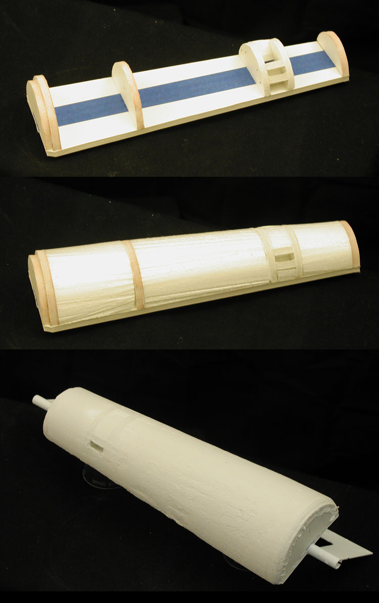
It started with cutting out pieces of foamcore board and building a base structure. Because this will be the master for both sides, I've included holes and alignment channels for both sides for the nacelle support pylons to slide into. It is easier to build the parts with both holes and fill in the extra later than to build it without any and add them later or build two of these. I'll be doing this exact same thing when I build the inboard nacelle master so I only have to build it once.
Next I put blocks of styrofoam in to the openings and used a hot wire to cut them to the general shapes I needed. And then with them glued into place, I used a template of the secondary hull shape to lay out a surface made of hydrocal. I let that dry/cure and then filled in any gaps that showed up.
This isn't all that different from how I made my primary hull for my one-sixth studio scale 11 foot TOS Enterprise, but I figured I'd show how these same steps could also be used to make a little more complex shape... so here is the start of the (pre-)master to the secondary hull of my Phase II Enterprise kit.
Phase II Enterprise Kit secondary hull master - start
It was made the exact same way, just requiring a different template for the shape and the alignment of the slots for the nacelle support pylons (which are at a different angle). And this is them together...
Comparison of secondary hull masters - earlier stages
And no, this model (the studio scale 33 inch TOS Enterprise) is not going to become a kit... nor could it's parts be used to convert the Round 2 1/350 TOS Enterprise (which is smaller than this model by more than an inch... 32.4 inches compared to 33.75 inches).
Once the hydrocal completely dries/cures I'll add on a surface that I can work to a smoother finish. When I'm all done, I'll make a mold and cast two parts (port and starboard halves).
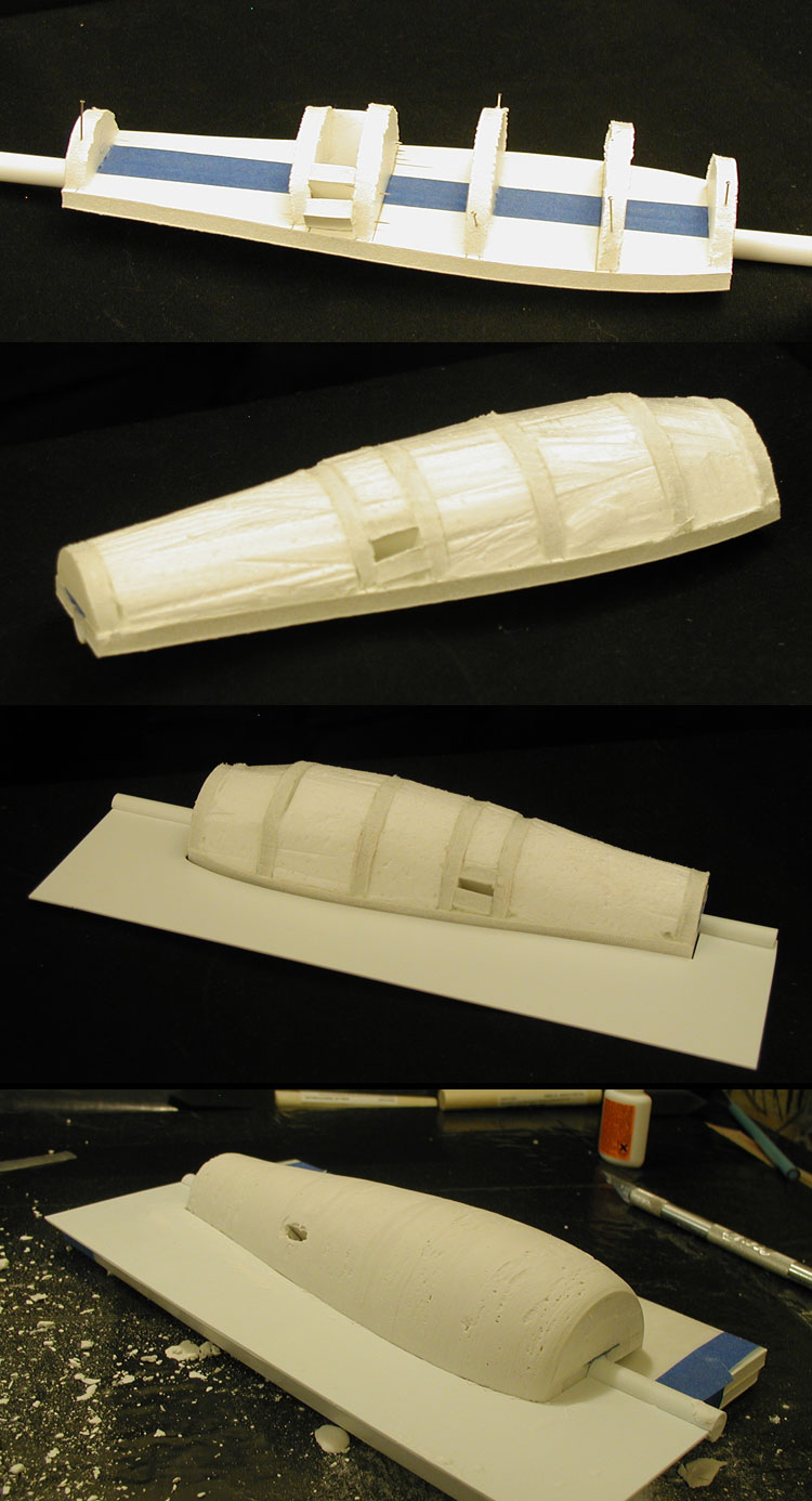
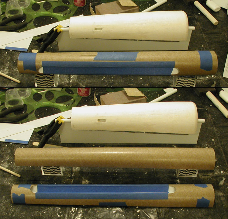
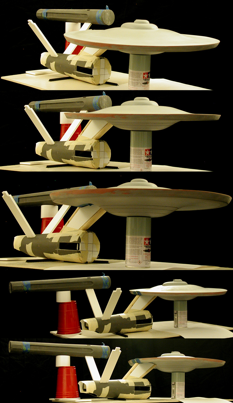
The next big step was to start in on the nacelle masters. For these I made a pattern for the inboard and outboard halves and cut them out of model rocket tube of approximately the right size. The patterns were designed to give me the taper I needed.
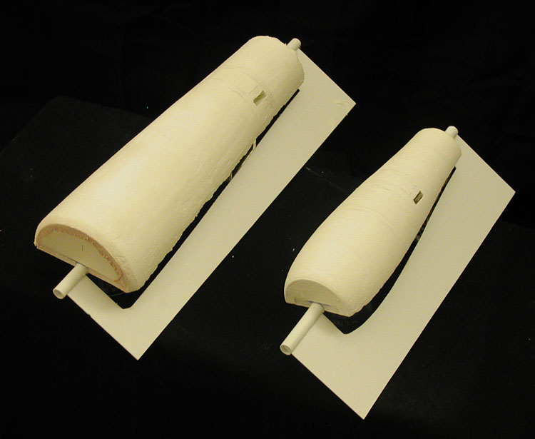
Below are shots of the start of the inboard and outboard nacelle masters, first together and then separate.
Nacelle masters - early stages (with secondary hull master)
There isn't a lot of stuff going on with the outboard master. The inboard master has the channel (which is shown started) and the attachment points for the nacelle support pylons. So there is going to be a bit of work needed to engineer all that before I get anywhere close to making molds.
A lot of this is going to look like the 11 foot model, but I'll point out where the 33 inch model differs as it becomes easier to see. One thing that is different here is that the inboard channel extends further back (running into the rear rectangular box features).
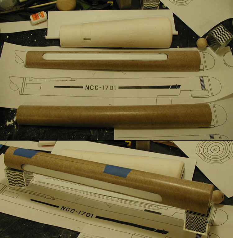
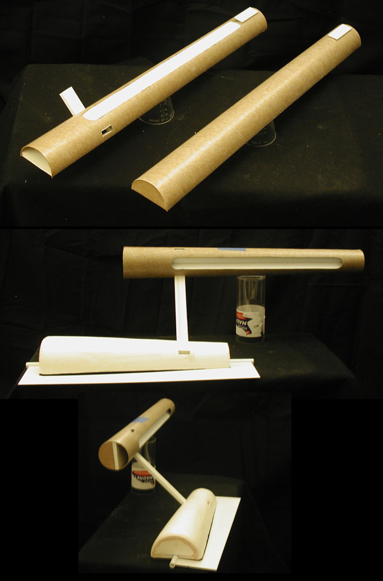
I continued to make some more progress on the nacelles, mainly gluing many of the inboard nacelle parts together.
Nacelle masters - progress
I cut the openings and started the slots for the nacelle support pylons attachment points. These slots are intended to help align the parts and are the same size as those on the secondary hull master. I cut out a piece of foamcore board that fit into those channels and tested the nacelle masters together with the secondary hull master to see how things are working.
Nacelle masters - support pylon slots
The secondary hull master is on it's side, but the main thing I was looking for was the center line of the masters to be parallel to each other... which it looked like it was when I tested it (for both sets of slots).
I've left myself enough maneuvering room to make adjustments with the final parts later on, but I wanted to have the masters (and molds) be as close to a perfect fit as I could (specially given that all this is hand made... but then again, so was the original model).
I haven't documented most of what I've been doing as it is essentially the same things I did on my one-sixth studio scale 11 foot model.
Here are some progress shots...
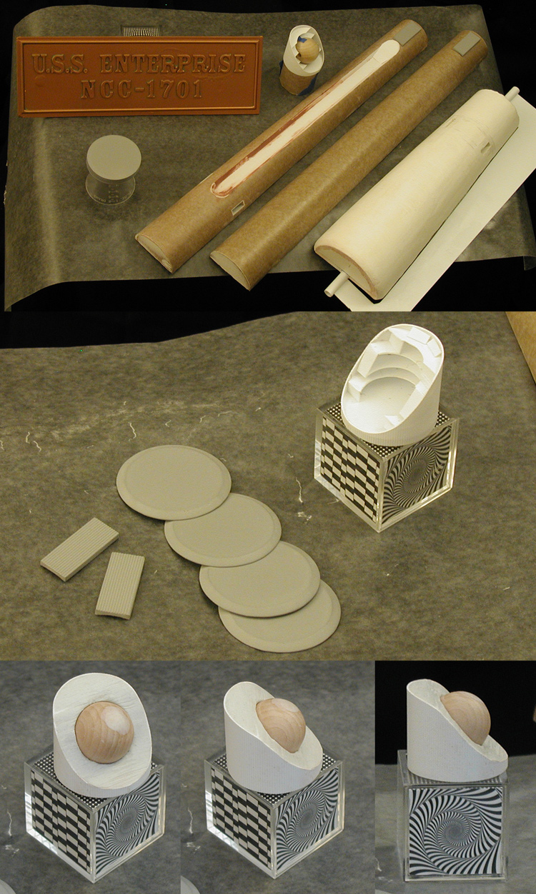
Masters - beginning of nacelle end masters
I included a test pull of my Enterprise name plaque (which I kept to try out painting/aging ideas on). There has been some more work on the inner nacelle channel, mostly sculpting the ends.
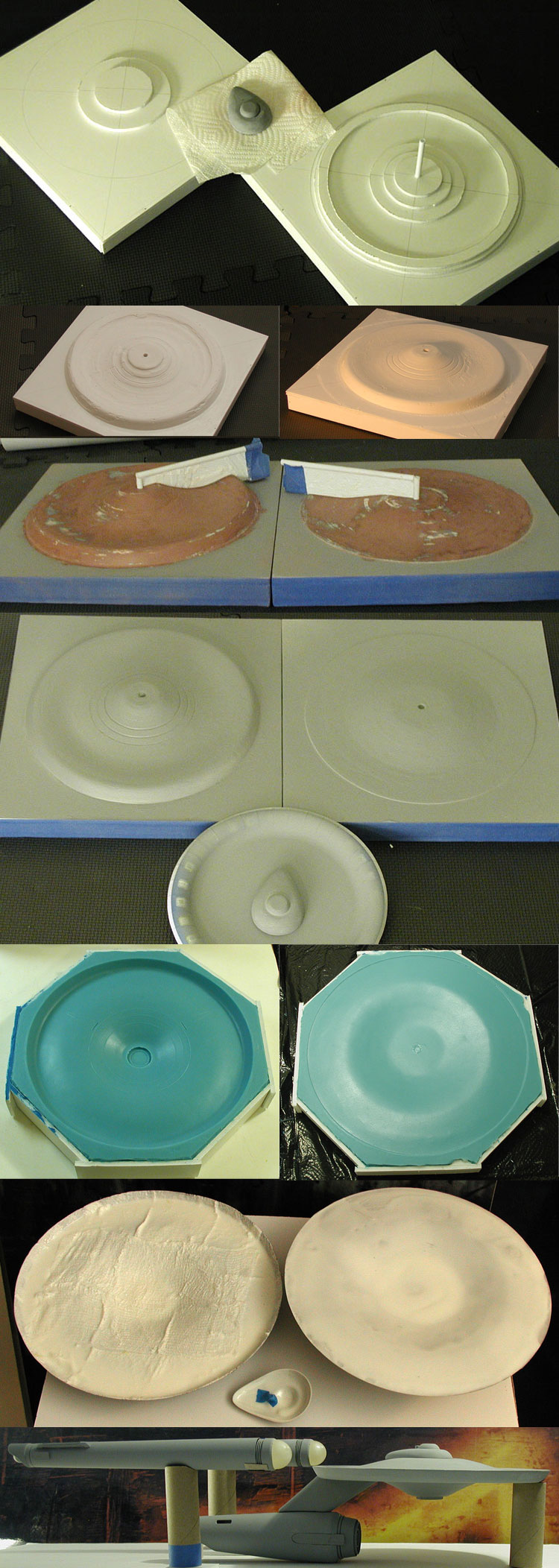
I started making the forward rings (which are currently just four disks). Building those is pretty straight forward... cut out a disk of thin styrene and a smaller disk of thick styrene, glue them together and fill in the stair step between. It doesn't take much effort and when I put all four together I get what I needed.
Because it took longer to do, I did take a series of images of the rear nacelle cap being constructed. For this I cut three disks... two were annulus, with holes large enough for the rear cap's sphere. I cut the annulus into two parts off center which gave me a total of five structural pieces to help hold the ribbed outer styrene sheet in the form of a cylinder. I later added a few more pieces of styrene to close up some openings and then used Aves apoxie sculpt to fill in the remaining open face... being sure to keep the hole needed for the sphere.
And again, these are all masters... none of these parts are going to actually be on the final model. This model will be made mostly of TC-1630 A/B UltraCast and Alumilite White, but for the masters, what ever works to make the shape.
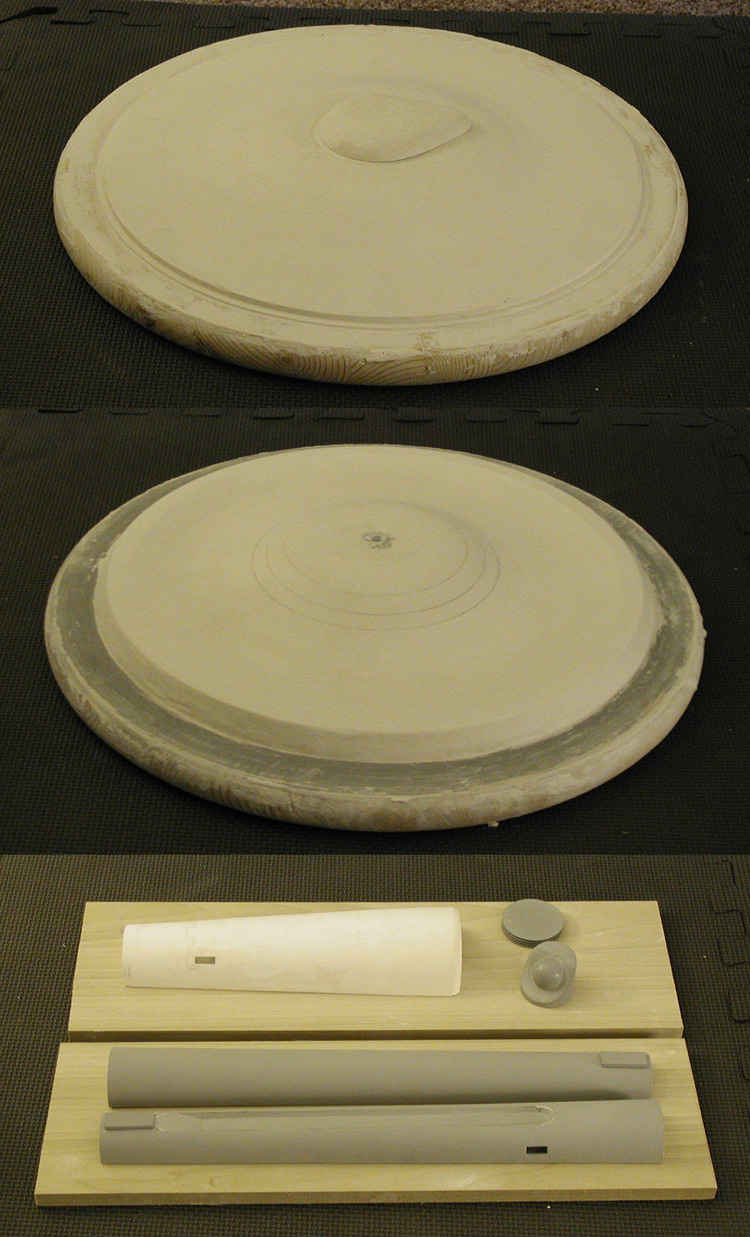
I've done some work on the nacelles and started on the primary hull masters. The nacelle halves and secondary hull half will be mounted to wood boards before I make the molds (though they aren't mounted just yet).
Primary hull masters and nacelle masters
I'm using 18 inch circular table tops as the bases for the upper and lower primary hull masters. I'll be using hydrocal on those to get the primary shapes I need.
A great tutorial on how I'm making some of these shapes can be found here.
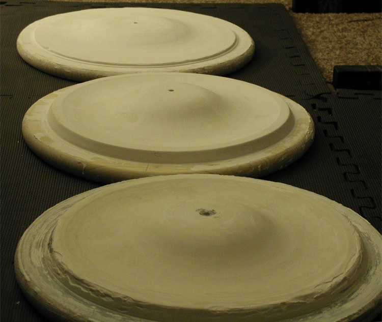
This is a little progress on the lower primary hull master...
Lower primary hull masters - early
I realized I need to fix a flaw in the pattern piece, and I noticed that one of the boards I was using warped, so I decided to build two lower primary hull masters and see which one turned out the best.
Primary hull masters
The top primary hull master is now at about 95% done in that shot. Right now (since that last photo) both lower primary hull masters are looking very good (though I'm most likely not going to use the one on the warped board).
That is about where I'm currently at.
33 inch TOS Enterprise - Studio Scale Replica
Moderators: Joseph C. Brown, Moderators
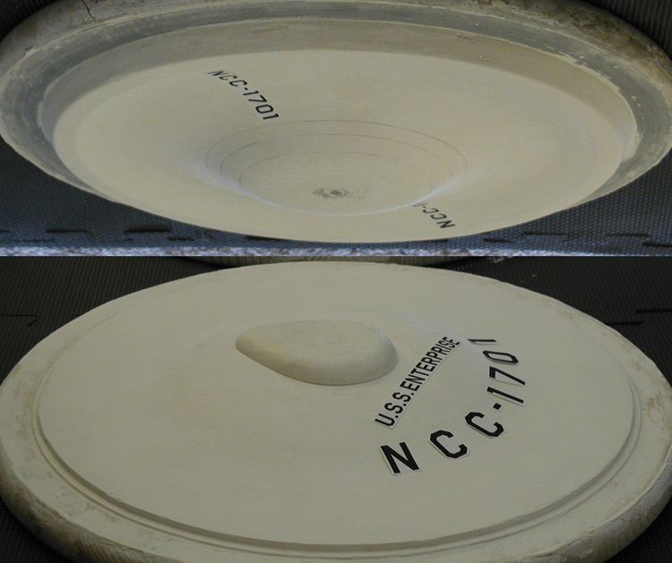
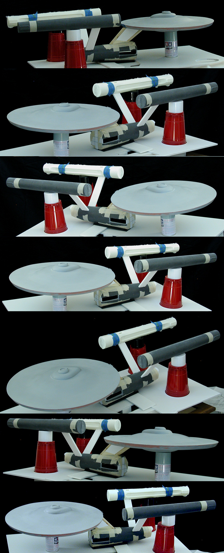
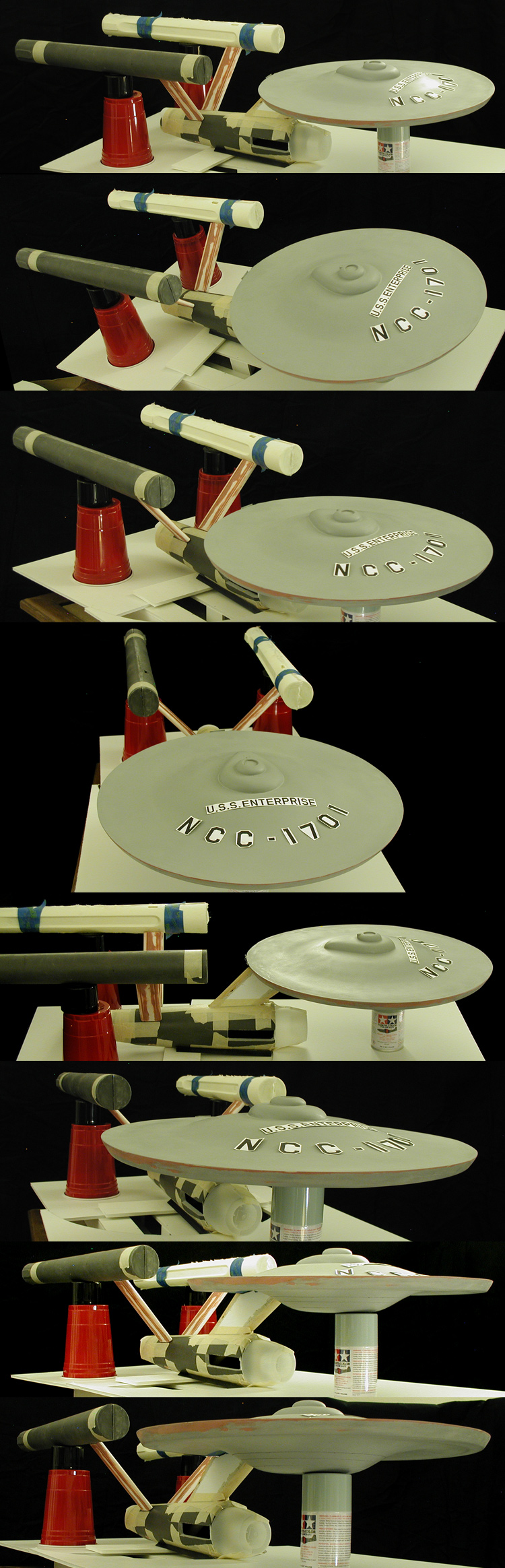
I've drawn on the underside rings to make sure that they match up with all my research. The best thing is that the NCC-1701 decals that go between the engraved rings and flat edge fit perfectly compared to photos of the original model, so I'm happy with them.
In this set of progress shots I've included the start of the B/C deck structure on the top primary hull master to get a feel for how it is progressing.
Progress shots
And this is a test placement of the decals on the masters.
Decal placement test
In this set of progress shots I've included the start of the B/C deck structure on the top primary hull master to get a feel for how it is progressing.
Progress shots
And this is a test placement of the decals on the masters.
Decal placement test
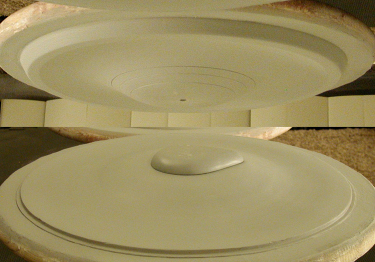
Recently I've been mostly puttying, sanding, primering and then repeating the process... attempting to get the surfaces to the best state I can.
Here is some progress on the primary hull masters (the lower rings have been engraved)...
Progress- primary hull masters
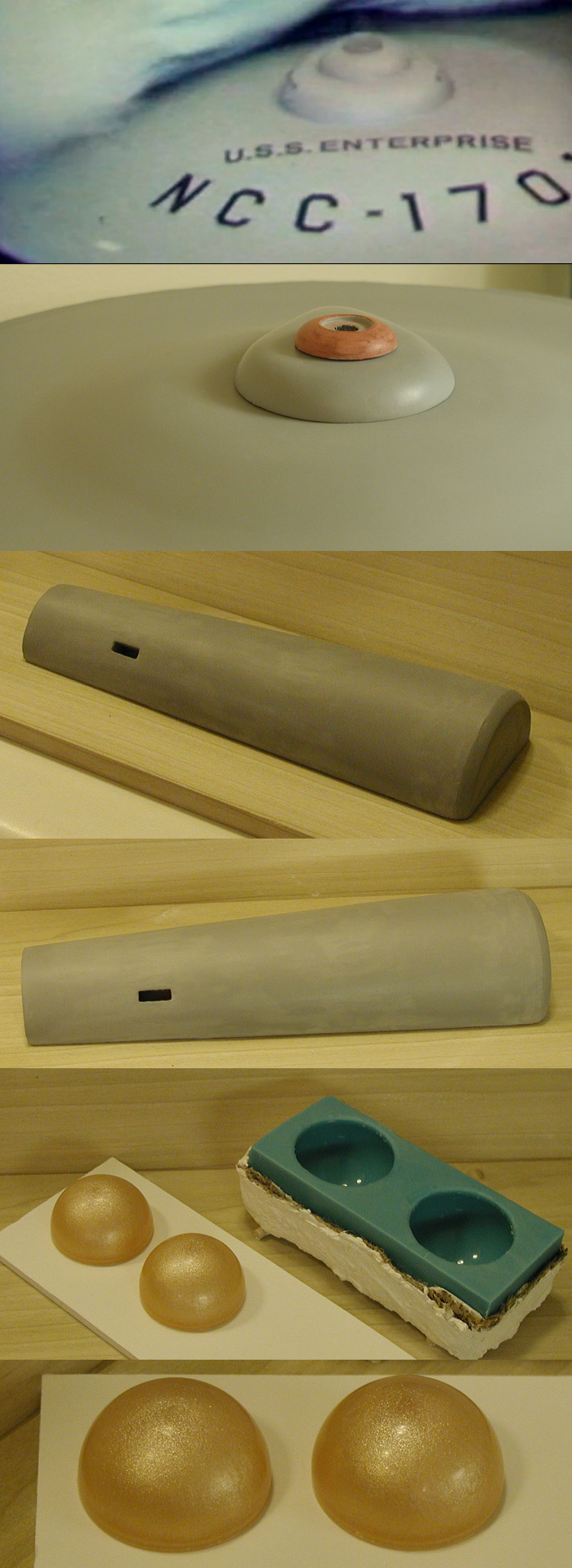
I've also started in on the bridge and done some more work on the secondary hull master. I included a shot of the original model for comparison in the series of images below. Both the bridge and the B/C deck structure are riding a little high, they'll sit lower and flush to each other (and later the upper primary hull with the actual parts) as I get closer to finishing them.
The biggest thing is that I pulled my first parts for the model... the nacelle domes.
Progress- bridge and secondary hull masters, nacelle domes
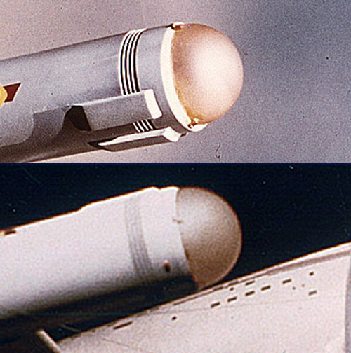
These are the main references I've been using for the domes...
Nacelle dome reference images
Here is some progress on the primary hull masters (the lower rings have been engraved)...
Progress- primary hull masters
I've also started in on the bridge and done some more work on the secondary hull master. I included a shot of the original model for comparison in the series of images below. Both the bridge and the B/C deck structure are riding a little high, they'll sit lower and flush to each other (and later the upper primary hull with the actual parts) as I get closer to finishing them.
The biggest thing is that I pulled my first parts for the model... the nacelle domes.
Progress- bridge and secondary hull masters, nacelle domes
These are the main references I've been using for the domes...
Nacelle dome reference images
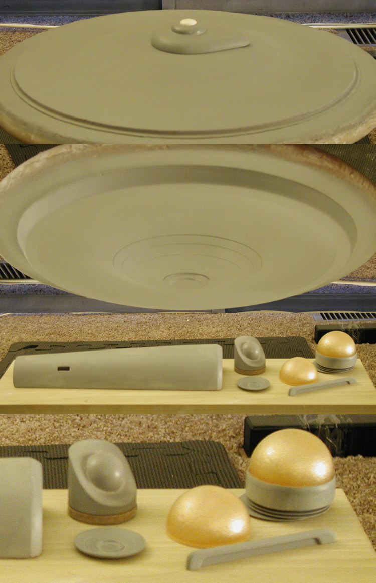
I've made the bridge and B/C deck structure into a single piece (the dome in the images below is a stand in for sizing purposes). I continued work on the rear nacelle end cap assembly and made quite a bit of progress on the front nacelle end cap assembly (now that I have nacelle domes). I've also started in on the lower sensor dome platform, intercooler and deflector masters.
Progress on masters
I've continued to work on the surface of the upper and lower primary hull masters, the secondary hull master and the nacelle masters, and I'm feeling pretty good about their progress. I figure I'm not too far off from making molds from those parts.
Here is a test assembly of the rear nacelle parts to see how those parts are coming together...
Test assembly of rear nacelle masters
Still a work in progress, but at least it sorta looks like what it is supposed to be.
Last edited by Shaw on Thu Jan 01, 2015 10:28 pm, edited 1 time in total.
-
Mr. Badwrench

- Posts: 9587
- Joined: Fri Jul 12, 2002 6:31 pm
- Location: Wheatridge, Co.
Thanks!
Yeah, it solved a ton of problems for sculpting those surfaces.
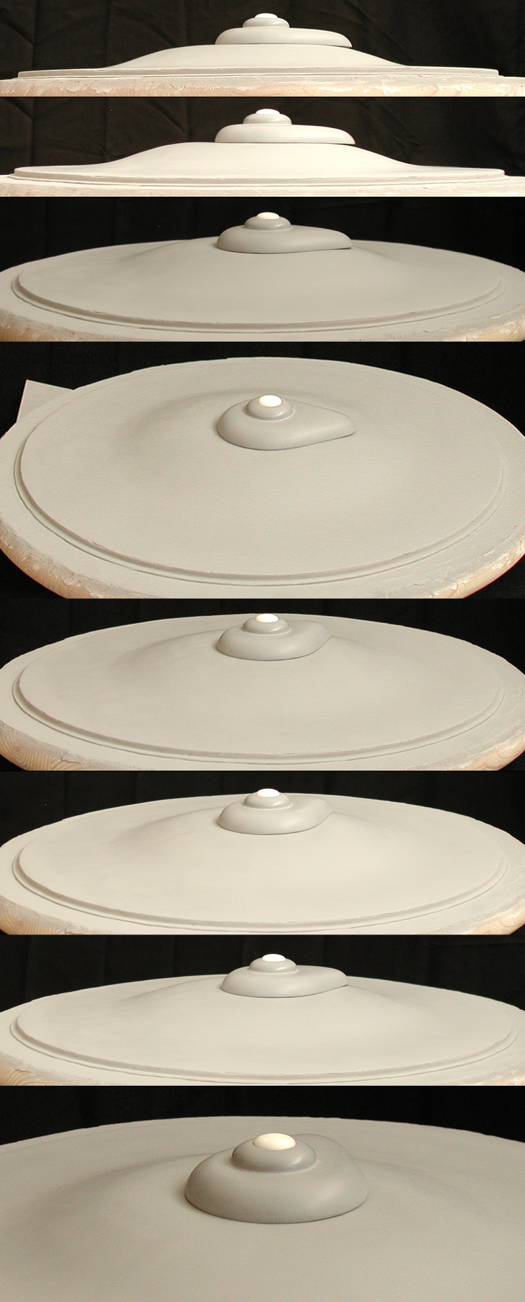
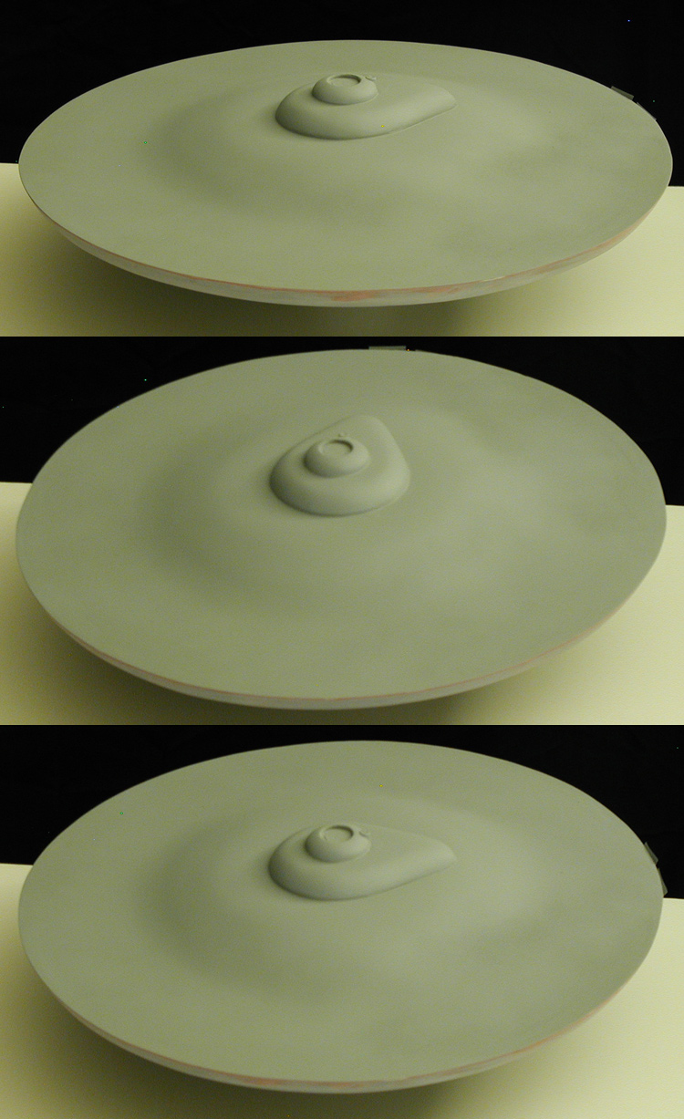
Here is a series of images of the upper primary hull with the bridge/B/C deck structure sitting in place to see how things are going with these parts...
Upper primary hull master with bridge/B/C deck structure
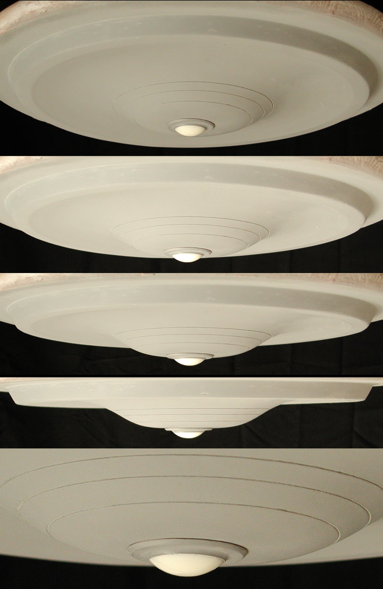
And another series of the lower primary hull with the sensor dome platform (and a stand in dome) in place...
Lower primary hull master with sensor dome platform
For both the upper and lower domes I'll be casting them in clear with a small amount of transparent green. I don't have transparent green dye right now, so I'll have to wait to actually make the final parts.
I think I'm almost ready for making molds of all these masters. There is just a handful of little things to fix/finish and they should be ready to go. Some aspects of the model just can't be done with the masters, so I need the final parts to go forward.
Yeah, it solved a ton of problems for sculpting those surfaces.
Here is a series of images of the upper primary hull with the bridge/B/C deck structure sitting in place to see how things are going with these parts...
Upper primary hull master with bridge/B/C deck structure
And another series of the lower primary hull with the sensor dome platform (and a stand in dome) in place...
Lower primary hull master with sensor dome platform
For both the upper and lower domes I'll be casting them in clear with a small amount of transparent green. I don't have transparent green dye right now, so I'll have to wait to actually make the final parts.
I think I'm almost ready for making molds of all these masters. There is just a handful of little things to fix/finish and they should be ready to go. Some aspects of the model just can't be done with the masters, so I need the final parts to go forward.
Some progress...
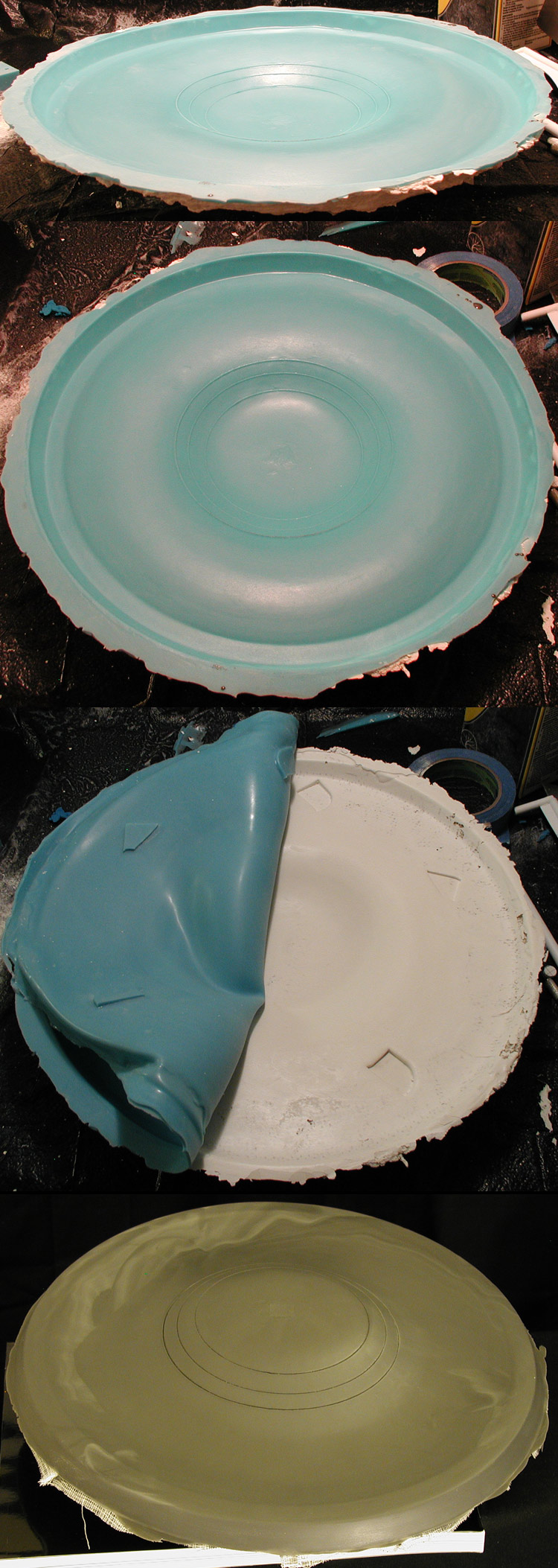
Made a mold of the lower primary hull and cast the first part from it (though I'm not sure if this is a final part or just a test)...
Lower primary hull mold and first pulled part
At least I know the mold produced a nice part and is still in great shape. The material (TC-1630 UltraCast) is really hard... much harder than Alumilite White. Having let the part fully cure for 24 hours, I don't think I needed to make the surface as thick as I did (the stuff is also very heavy). The nice thing is that I'm not as worried about flexing in the secondary hull were the nacelle support pylons will attach.
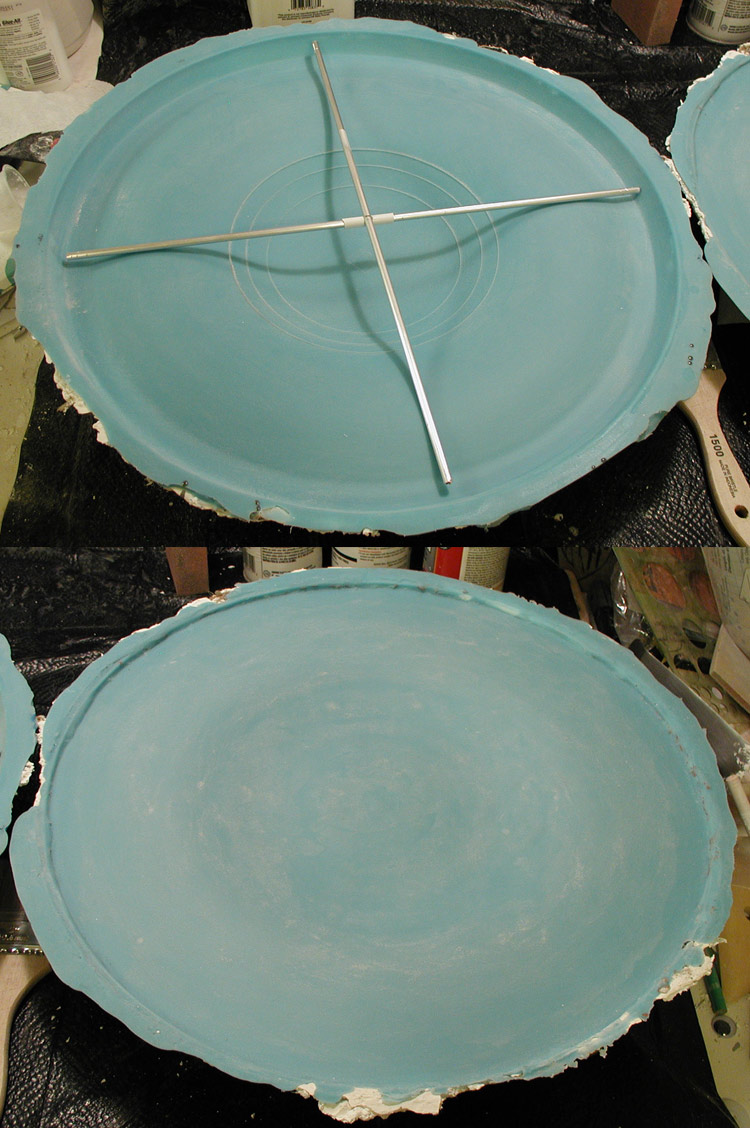
I finally have molds for both the upper and lower primary hull.
Lower and upper primary hull molds
Hopefully I'll have parts by the end of this weekend. The nice thing is that I really don't need to get inside for anything, so I can close the primary hull up pretty quickly. The big issue with this would be getting a nice, sharp upper lip edge.
We'll see how things go.
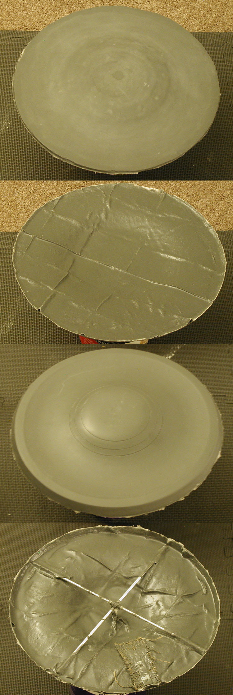
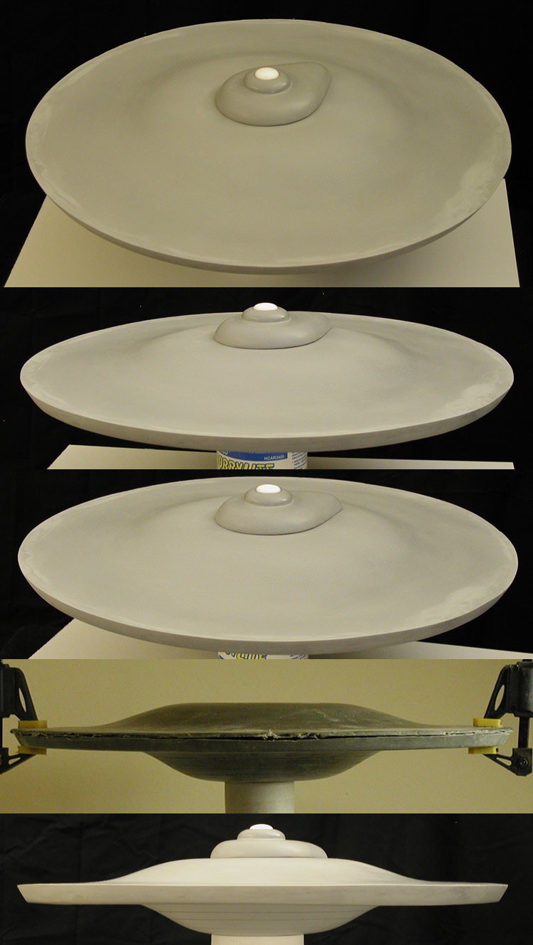
And I now have primary hull parts!
Upper and lower primary hull parts
The best part of this is that these two halves weigh about the same as the first lower primary hull pull I did.
I cleaned up the edges (this is the primary hull top with the first lower half so I could experiment with cutting) to see how things fit together...
Primary hull test fit
Still a bit thicker than it should be, but at least it is really starting to feel the part.
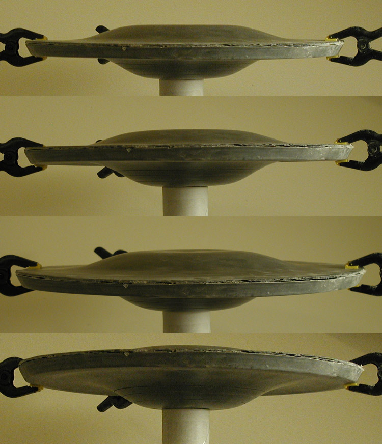
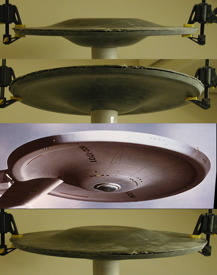
Based on what I learned from the spare lower primary hull, I cut down the main lower primary hull and did a test fit of the top and bottom together...
Primary hull halves, test fit
I threw in a shot of the original model from approximately the same angle for comparison. The clamps aren't actually clamping in those images. I had set them to the target thickness I was aiming for for the outer edge. They pretty much freely slide around the rim at this point.
Ummm... so is anyone actually reading this thread?
-
admiralcag

- Posts: 975
- Joined: Fri Jun 20, 2003 6:46 am
- Location: Arvada, CO
-
Joseph C. Brown

- Moderator
- Posts: 7301
- Joined: Thu Jul 11, 2002 6:13 pm
- Location: Oak Ridge, TN, USA
Cool! Thanks guys. I knew if I put this thread in this section it would at least have a longer life than in the Star Trek section (I had a long thread detailing the building of my Phase II Enterprise over there and it disappeared right as I was getting ready to post an update).
I've put a little more work in on this model, I got the upper and lower halves of the primary hull together, this is my first primer pass to see how my putty work turned out...
Primary hull, first primer pass
There is still a bit of refining to do, but I'm pretty happy with the results so far.
I've put a little more work in on this model, I got the upper and lower halves of the primary hull together, this is my first primer pass to see how my putty work turned out...
Primary hull, first primer pass
There is still a bit of refining to do, but I'm pretty happy with the results so far.
Thanks!
About to start another round of putty/sanding, but here is some shots of the top of the primary hull (with the bridge/B/C deck master set in place)...
Primary hull top, progress shots
Still a long ways to go, so back to my grindstone.
About to start another round of putty/sanding, but here is some shots of the top of the primary hull (with the bridge/B/C deck master set in place)...
Primary hull top, progress shots
Still a long ways to go, so back to my grindstone.
Some more progress...
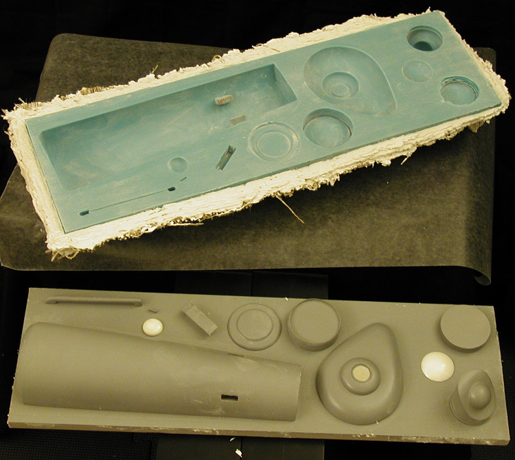
This is the mold for the secondary hull halves, bridge/B/C deck structure and some of the nacelle parts along with the masters used to make it...
Secondary hull, bridge/B/C deck structure and nacelle parts mold
Some shots of the final bridge/B/C deck structure in place (still working on blending the seam)...
Primary hull progress shots
And I started on making the parts for the dorsal... this is a test assembly of them to make sure that they fit to the primary hull's contour.
Primary hull with dorsal, secondary hull pull
I included a shot of my first pull from the secondary hull mold. I don't know if that is going to be an actual part for the model, but at least I got the shape I was looking for.
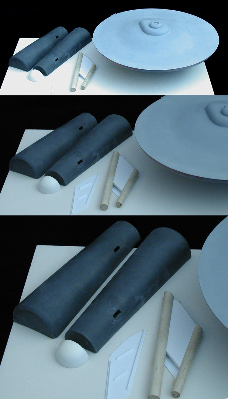
I now have the start of the secondary hull, including the start of the hangar doors (yes, my model will have the hangar doors even though the original model's doors were lost between the second and third seasons of TOS)...
Primary hull, dorsal, secondary hull parts
The goal is to replicate the model at it's most iconic period... when being used for publicity photos with the cast members during the first season. Some time between the second and third seasons the model was dropped and imperfectly repaired (the port side nacelle was re-attached wrong and the outboard intercooler on the starboard nacelle was glued on backwards) along with the hangar doors being lost.
Small update...
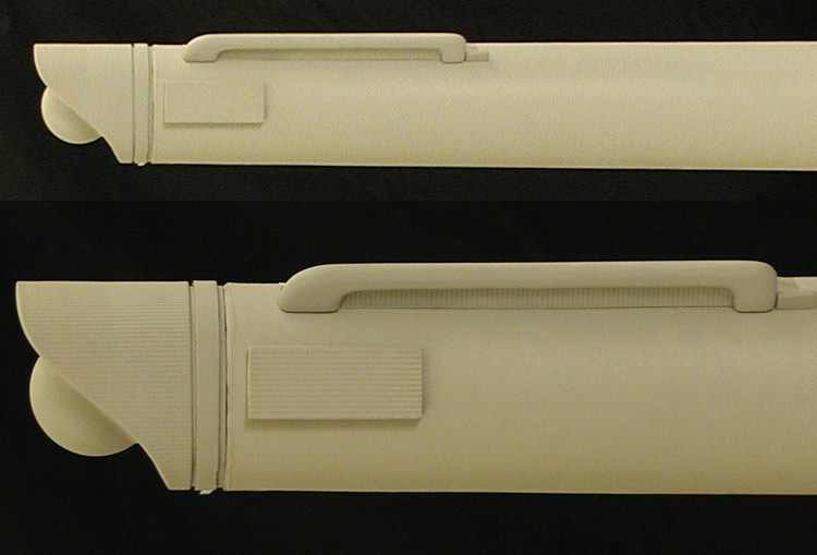
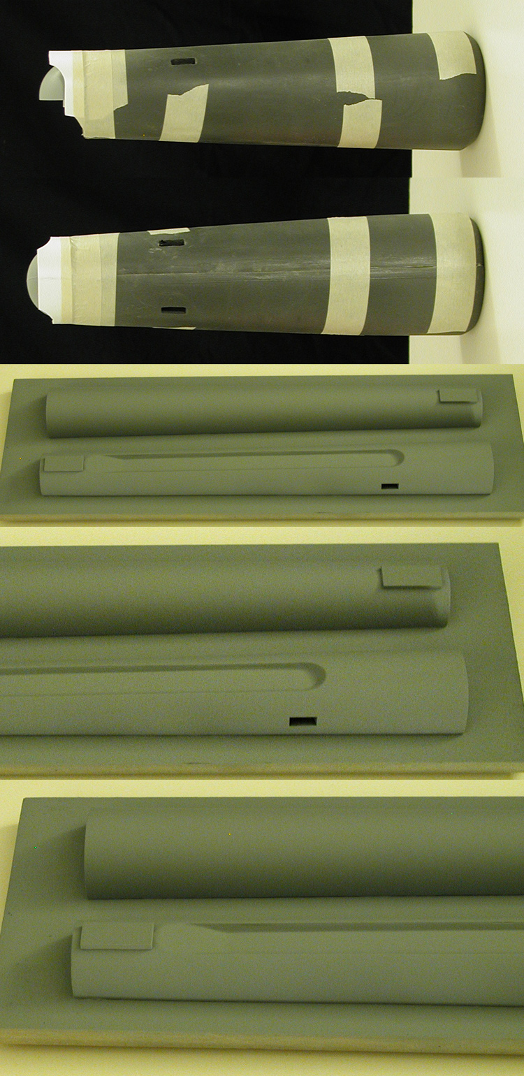
Did some trimming of the secondary hull halves an test fit them with the start of the hangar door hood. There is still a ways to go, but it is feeling like I'm making progress.
I also finished up the nacelle masters and mounted them to a board. I hit them with a couple coats of Krylon Crystal Clear before starting in on making a mold.
Test fit of secondary hull, nacelle masters
I finished up with the silicon rubber part, now just making the mother mold for the nacelles.
I also did the first major cuts into the secondary hull... the rear undercut and the side channels.
This is a good example of why my parts aren't kit friendly. The secondary hull was no where even close to finished when I made the mold, but that was by design so I only had to worry about turning out one side to get both. And I knew what I'd have to do to finish the secondary hull as a whole.
This is after a couple hours of cutting/shaping...
First major cuts to the secondary hull
The nice thing is that I was totally pounding away at these parts, and they are very strong. They are also very rigid...which is also quite nice.
Another update...
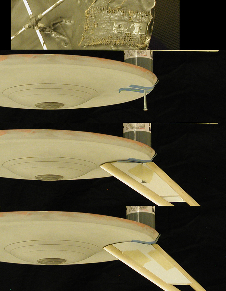
Did some more work on the dorsal. The last major internal piece was mounting the locking screw (which corresponds to a metal plate I embedded into the lower primary hull piece back in January). I should be able to make pretty quick progress on the dorsal from here.
Dorsal, locking screw placement
Once I'm done with the dorsal, I'll build it into the secondary hull, locking it into place.
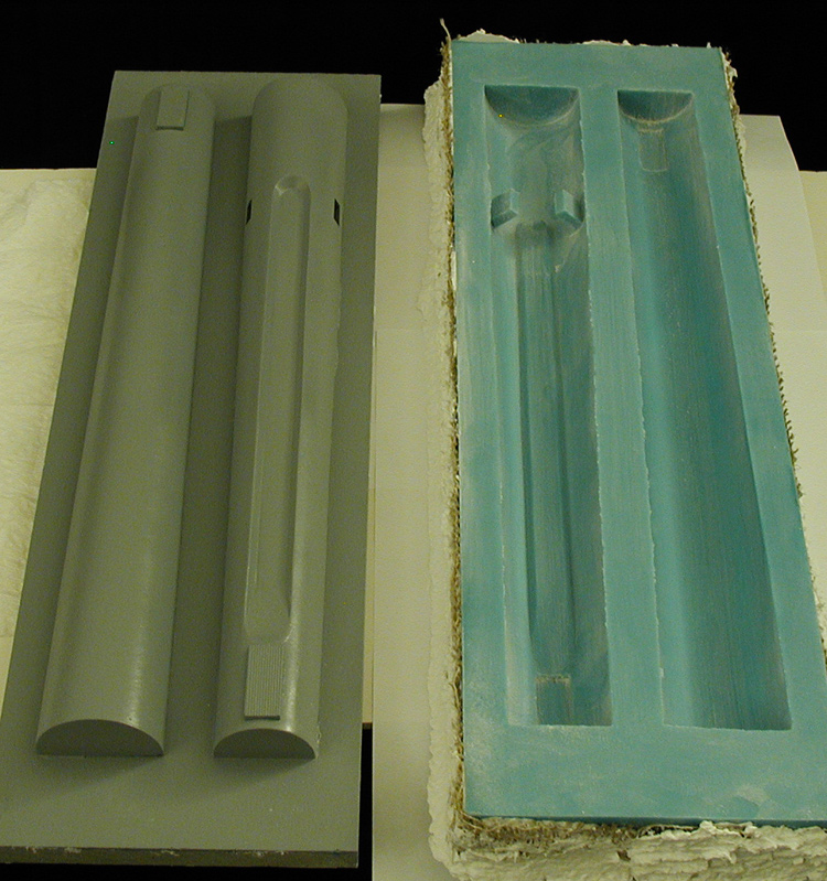
I finished making the mold for the nacelle body.
Nacelle body mold and master
I've also been testing fit and alinement of aspects of the secondary hull. With the dorsal set in place, I made some nacelle support pylon stand-ins out of foamcore board. I just needed to mimic the size and shape of the final parts to make sure that the slots they will eventually fit into will produce the correct angles...
Secondary hull alinement test
All the angles look pretty good at this stage. And if there had been nacelles on the pylons, their center lines would have been about 10 inches apart (like they are supposed to be)... so that is a sizable amount of work done early on while engineering the masters that has thankfully paid off.
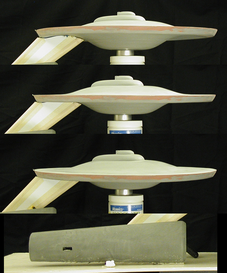
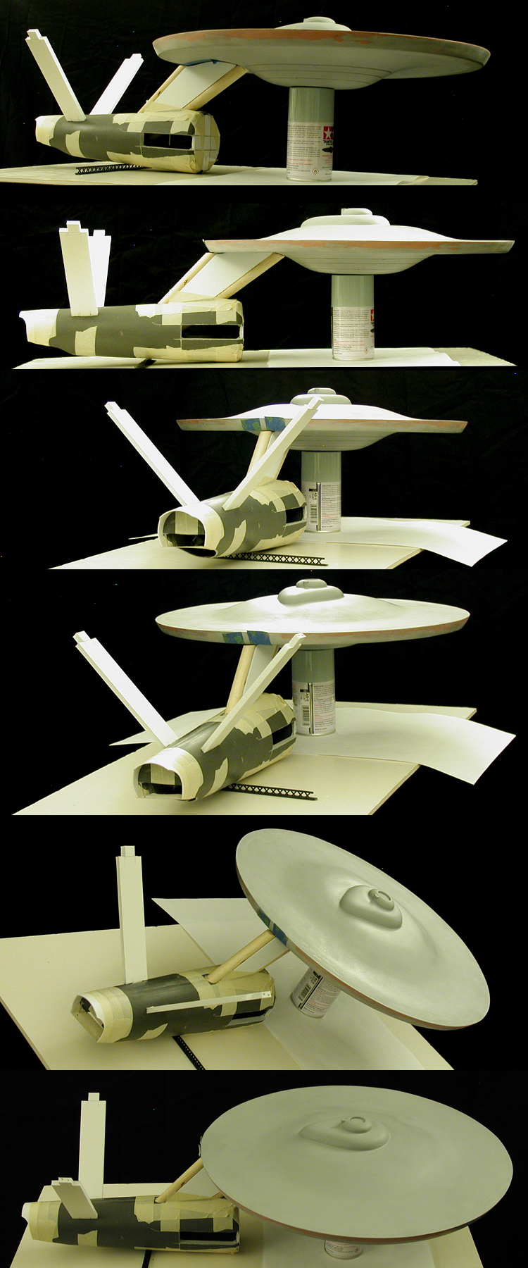
And I decided I really wanted to see how the parts looked in place too... so here it is.
Test assembly- secondary hull, primary hull
I did a quick test pull from the nacelle body mold, here is how it looked in place...
Test assembly- secondary hull, primary hull, first test nacelle
And I did a second test pull (this time using Alumilite White rather than TC 1630) to see which material I liked best. I'll most likely go with TC 1630, but I think I can get the total amount of material used down a bit more.
Still, it means I have two test nacelle bodies (though I didn't want to waste too much more time on the Alumilite White version), which makes for better test assembly shots...
Test assembly- secondary hull, primary hull, first and second test nacelle
The fact that all the main parts are able to come together in proper relation to each other, even at this early stage, lets me know that I haven't made any significant errors while making the parts. That makes it easier to move forward.
Did some more work on the dorsal. The last major internal piece was mounting the locking screw (which corresponds to a metal plate I embedded into the lower primary hull piece back in January). I should be able to make pretty quick progress on the dorsal from here.
Dorsal, locking screw placement
Once I'm done with the dorsal, I'll build it into the secondary hull, locking it into place.
I finished making the mold for the nacelle body.
Nacelle body mold and master
I've also been testing fit and alinement of aspects of the secondary hull. With the dorsal set in place, I made some nacelle support pylon stand-ins out of foamcore board. I just needed to mimic the size and shape of the final parts to make sure that the slots they will eventually fit into will produce the correct angles...
Secondary hull alinement test
All the angles look pretty good at this stage. And if there had been nacelles on the pylons, their center lines would have been about 10 inches apart (like they are supposed to be)... so that is a sizable amount of work done early on while engineering the masters that has thankfully paid off.
And I decided I really wanted to see how the parts looked in place too... so here it is.
Test assembly- secondary hull, primary hull
I did a quick test pull from the nacelle body mold, here is how it looked in place...
Test assembly- secondary hull, primary hull, first test nacelle
And I did a second test pull (this time using Alumilite White rather than TC 1630) to see which material I liked best. I'll most likely go with TC 1630, but I think I can get the total amount of material used down a bit more.
Still, it means I have two test nacelle bodies (though I didn't want to waste too much more time on the Alumilite White version), which makes for better test assembly shots...
Test assembly- secondary hull, primary hull, first and second test nacelle
The fact that all the main parts are able to come together in proper relation to each other, even at this early stage, lets me know that I haven't made any significant errors while making the parts. That makes it easier to move forward.
Over the last few days I've constructed the nacelle support pylons. They are actually pretty strong (stronger than I thought they'd be), and can support the weight of either test nacelle. Still, I'd like to get the weight of the final nacelle bodies down a bit more because there are a number of pieces which will eventually be added... adding weight to the nacelles. And even though most of them should be pretty light weight, the domes (which were finished a while ago) are solid and do have a bit of weight to them.
I took another series of test assembly shots, this time with a stand-in for the front of the secondary hull and placement of a test printing of the primary hull decals. I've done a little more work on both the secondary hull and dorsal, but nothing that is note worthy in these images...
Test assembly- primary hull, secondary hull, nacelle support pylons, first and second test nacelles
It is still pretty rough, but right now I'm mainly happy that all the major elements at least play nicely with each other.
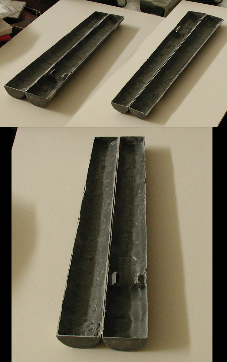
I figured I'd run through how I'm building these parts (as I mostly show them already together). Below is a shot of what the inside of one of the nacelles looks like...
Nacelle body interior
Here is a quick run down of the technique I use...
In the case of the TC-1630, I get about a 10 minute window of work time, so I spread a thin layer over the surface of the mold... making sure to brush it up towards the edges and the higher points. Pretty soon it starts to thicken, and when it stops easily flowing, I let it sit for a couple minutes. I then press in pre-cut sheets of fiberglass cloth, making sure it conforms to the interior contours (it has some give, and you can pre trim it to lay pretty flat against the mold's surface). I then mix up a second batch of TC-1630 and brush it over the fiberglass... making sure it gets absorbed into the material before it starts to set up. Once I get a good covering, I start brushing it up towards the edges like before.
The parts can be removed from the mold pretty quickly... though I usually give it a few hours. After six to eight hours it is pretty hard, after 24 hours it is rock solid (pretty much no-give)... which is why it works so nicely for these larger parts while letting the parts stay pretty thin.
The irregular surface on the interior of the nacelle is from the brushing up process. Irregular surfaces are actually stronger (more rigid) than smooth ones, so it acts sorta like a structural re-enforcement.
The TC-1630 actually cuts nicely too... this is why I wasn't too worried about leaving off key details on the secondary hull master so I could get away with a single master and mold to make both sides. Knowing what I was going to be working with ahead of time is why I knew I only needed one secondary hull half, one outboard nacelle body half and one inboard nacelle body half to build the secondary hull and nacelles.
Hopefully that clears up any confusion. I figured I'd share this with you guys in case anyone was curious.
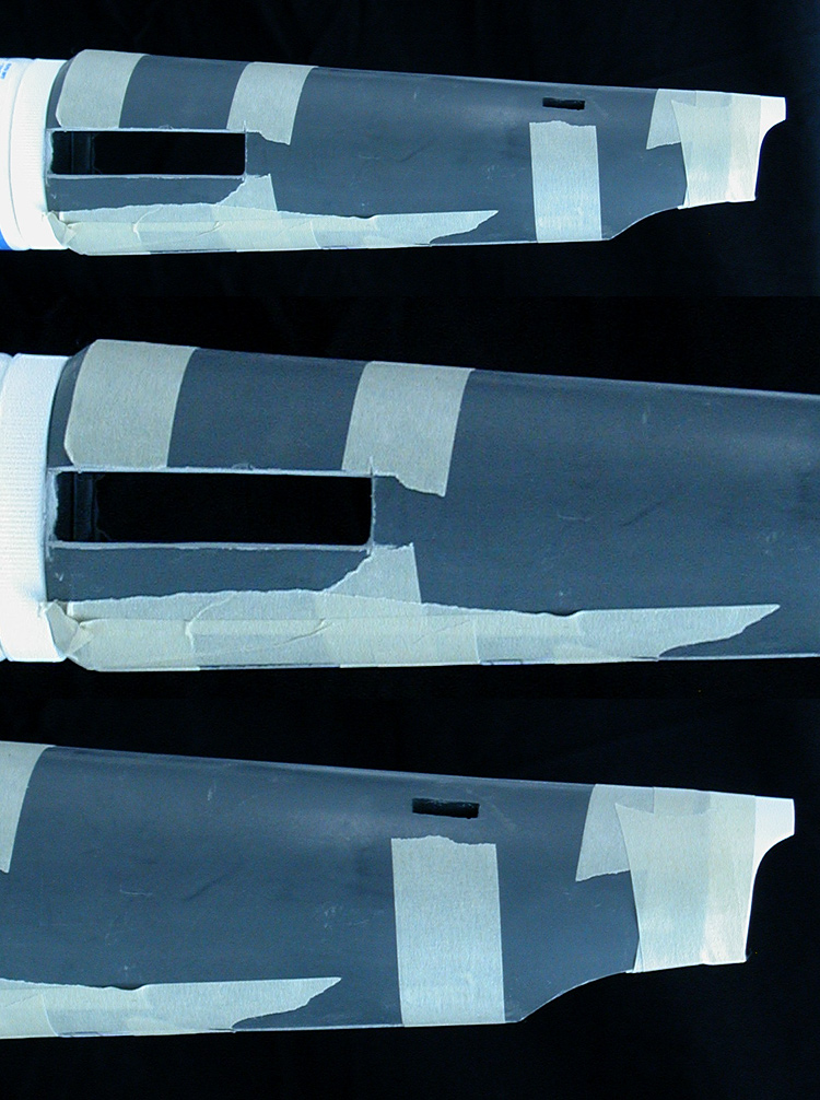
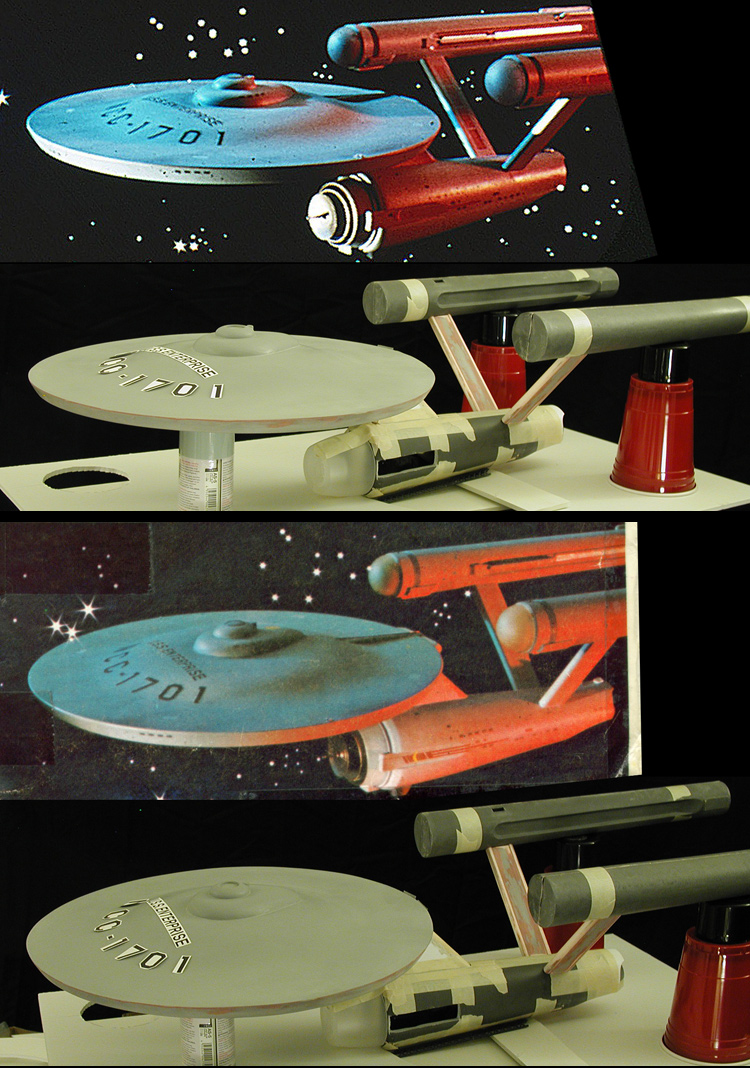
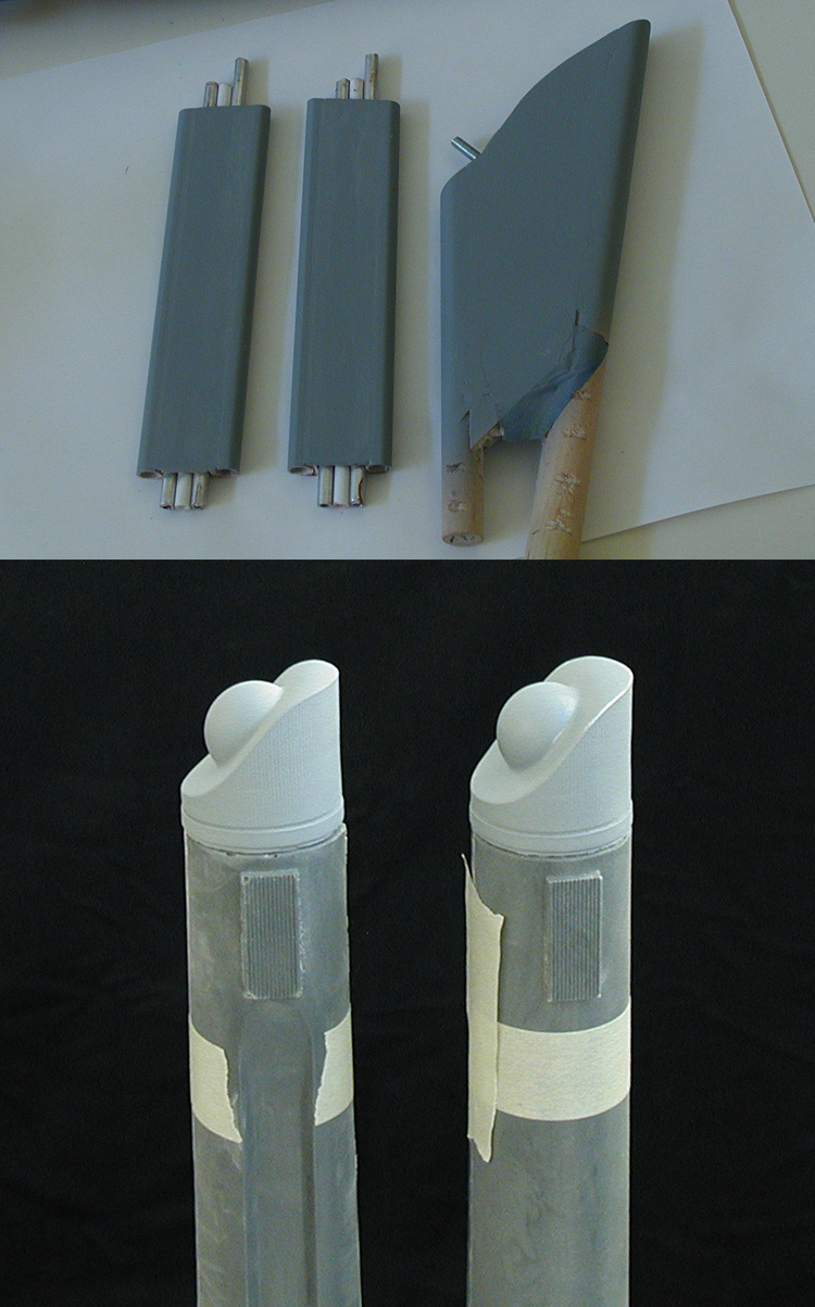
I've been working on a number of different parts of the model recently, mostly the deflector assembly, casting parts for the nacelles and making sure I'm happy with the dorsal and nacelle support pylons. I've also been working on the decals, so I've placed test printings of different decals on the model to compare what I have against photos of the original model.
This is a good example of some comparisons with the Viewmaster images of the original model...
Viewmaster comparison shots
Most of the work on the dorsal and nacelle support pylons has been making sure that the surfaces between where they connect to other parts are in good shape. It is easier to get them nice while they are still on their own. They still have quite a ways to go, but they are starting to look like they should.
Dorsal, nacelle supports and nacelle end caps
I started in on the nacelle parts with the rear end caps. Those came out pretty nice and shouldn't require too much additional work. The main thing I needed from them is to stand in place while I adjust the nacelle body when I bring it together.
I did a quick test assembly to compare some of the decal elements. Oddly, while the original builders of the model took the "U.S.S. ENTERPRISE" straight off the decal sheet, the smaller "NCC-1701" decals have had their spacing adjusted when they were applied to the original model.
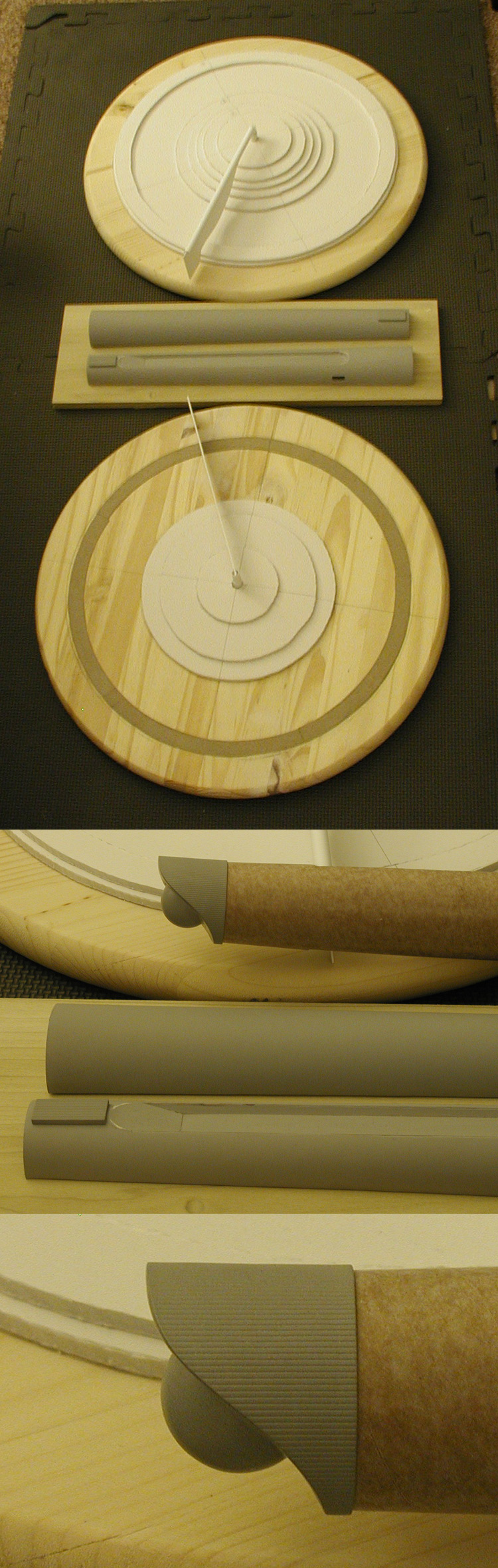
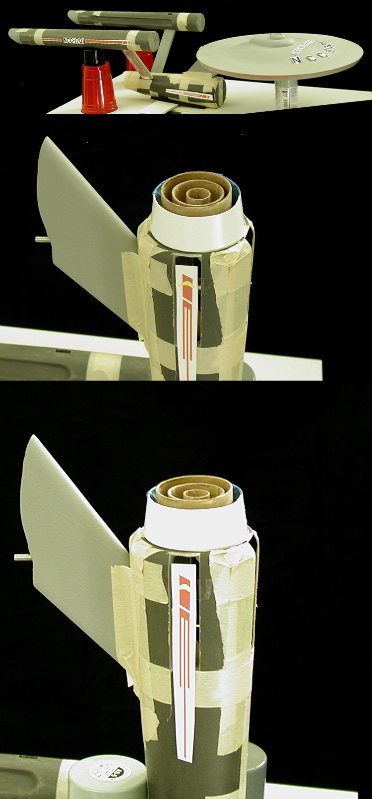
I realized after taking these shots of the deflector assembly parts that I had used the templates based on my original (2007) plans and not the updated ones... so the second of the three inner rings is too wide.
Start of the deflector assembly
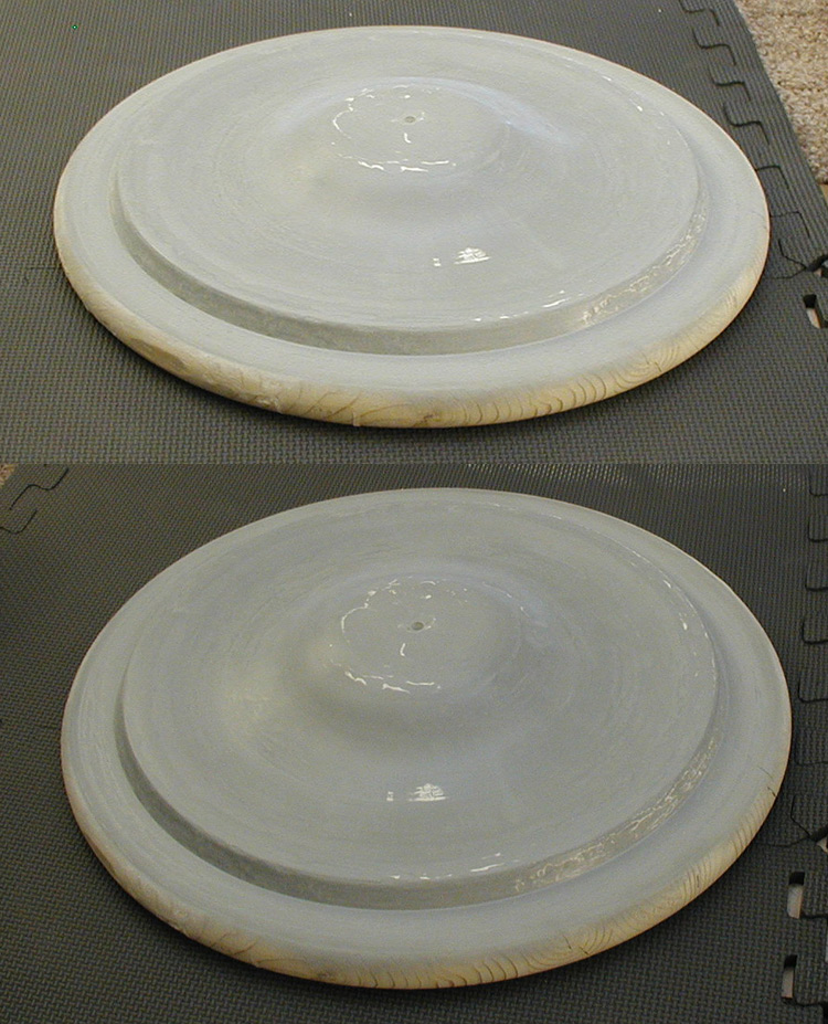
This is another couple shots of the deflector assembly with the start of a new second ring and the deflector dish master in place.
Additional deflector assembly work
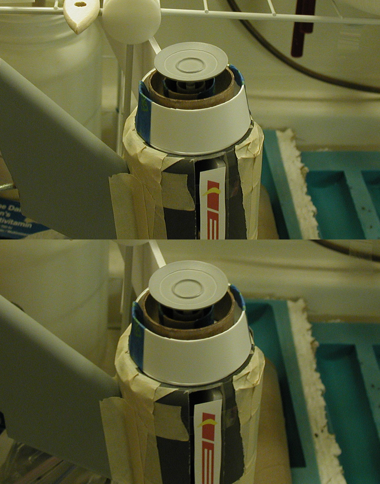
With a few more of the nacelle parts cast, I took another series of shots of the model assembled to see how things are coming together.
Test assembly- one nacelle dome and start of deflector assembly
One of the things I noticed about the secondary hull pennant on the original model is that the rear slopes downward (on both sides) compared to the center line of the secondary hull and the windows. I'll have to figure out how to replicate that without taking it too far as to be noticeable (which on the original it is hard to spot).
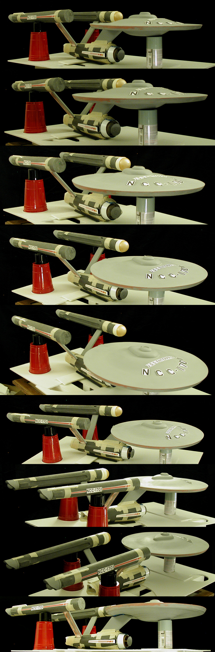
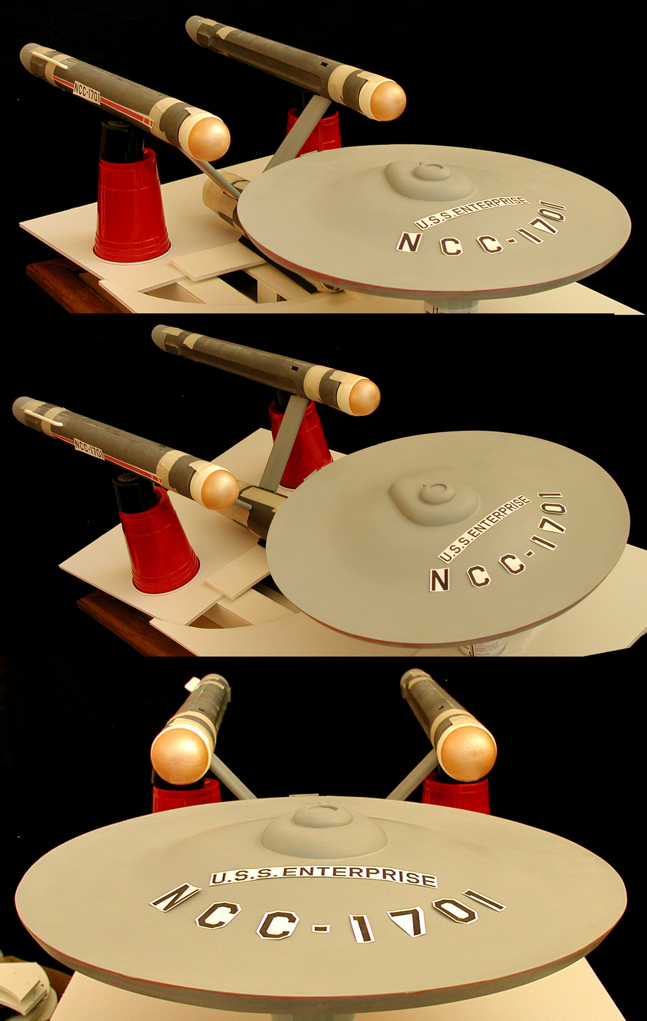
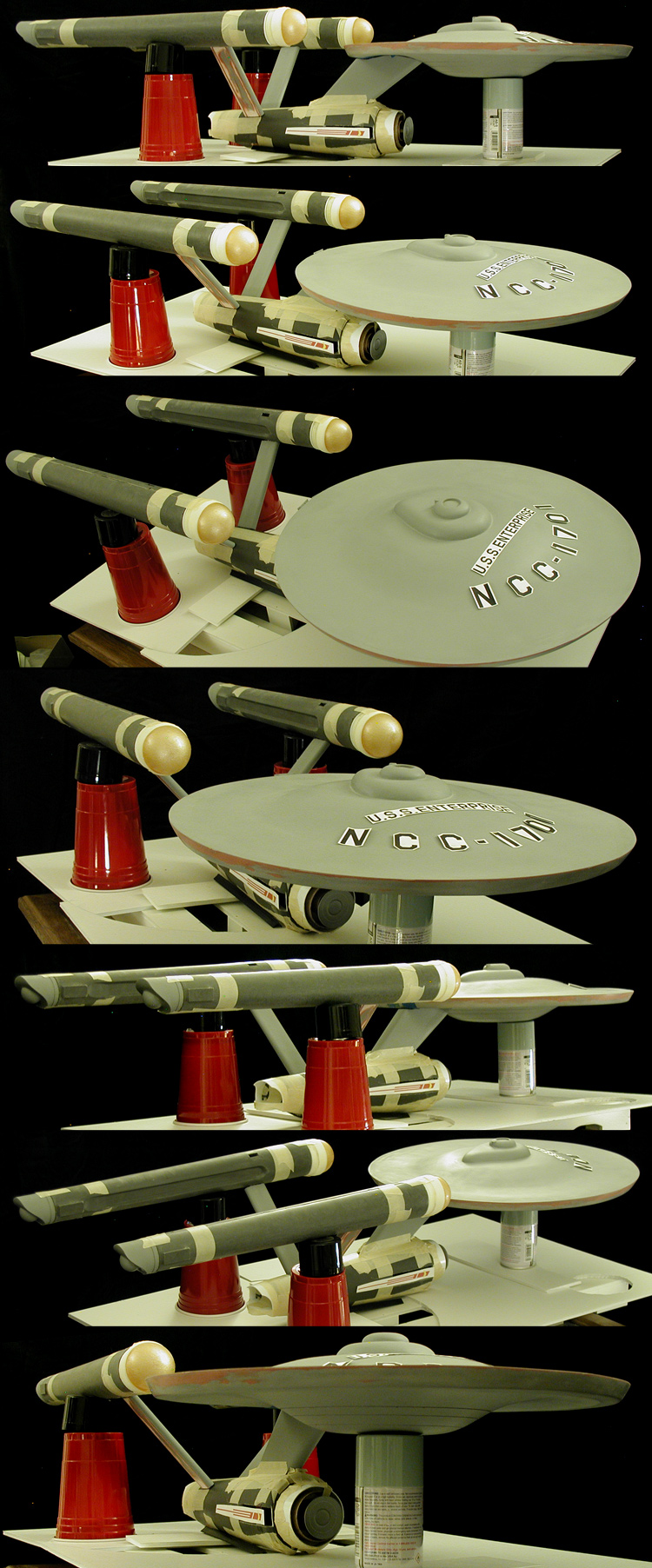
A few more test assembly shots... this time with both nacelle dome assemblies in place and deflector assembly (with most of the parts) attached. The first set is slightly higher resolution (but missing the deflector assembly)...
Test assembly- both nacelle dome assemblies
The next set is at my normal resolution...
Test assembly- both nacelle dome assemblies and deflector assembly in place
One of the things I noticed is that the nacelles seem better balanced with the dome assembly elements in place.
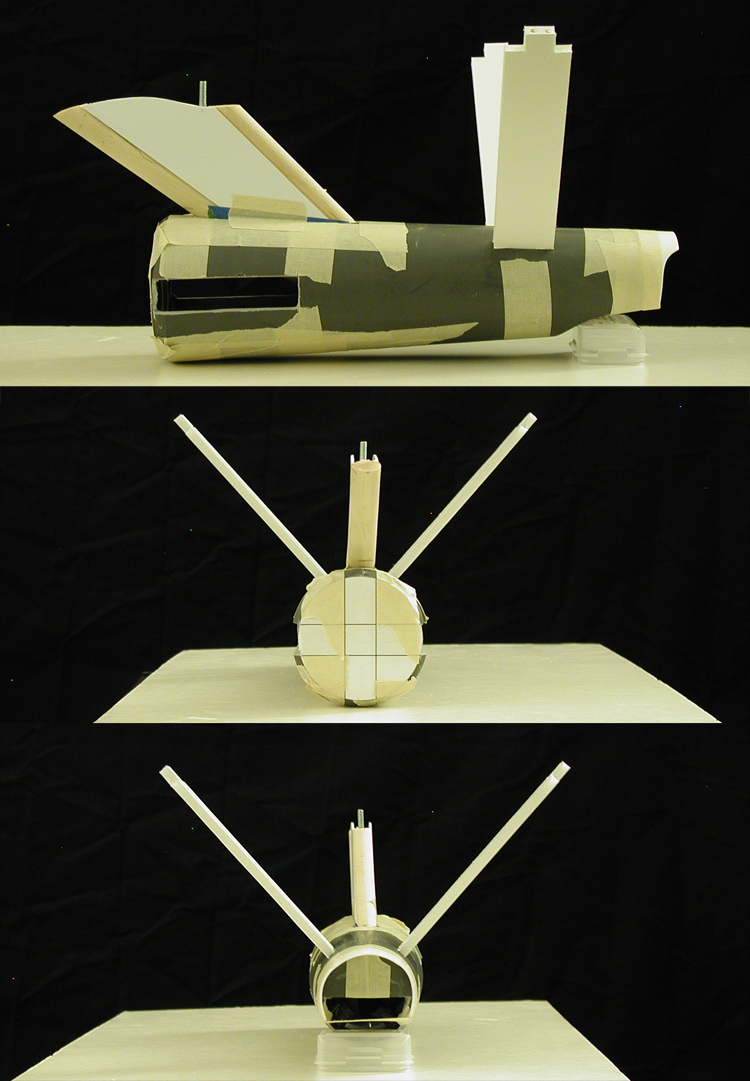
The next big step will be bringing the secondary hull together (rather than have the pieces taped together as they are right now). What I'll need to do to start that is build an alignment box much like the one I built for the Phase II Enterprise...
Phase II Enterprise alignment box example
This will help me make sure that the nacelles align with the primary hull, which is done via the secondary hull. The nacelles only need to be partly assembled and the primary hull is mostly assembled for these parts to correctly align the dorsal and nacelle support pylons in the secondary hull as I bring it together.
Nacelle body interior
Here is a quick run down of the technique I use...
In the case of the TC-1630, I get about a 10 minute window of work time, so I spread a thin layer over the surface of the mold... making sure to brush it up towards the edges and the higher points. Pretty soon it starts to thicken, and when it stops easily flowing, I let it sit for a couple minutes. I then press in pre-cut sheets of fiberglass cloth, making sure it conforms to the interior contours (it has some give, and you can pre trim it to lay pretty flat against the mold's surface). I then mix up a second batch of TC-1630 and brush it over the fiberglass... making sure it gets absorbed into the material before it starts to set up. Once I get a good covering, I start brushing it up towards the edges like before.
The parts can be removed from the mold pretty quickly... though I usually give it a few hours. After six to eight hours it is pretty hard, after 24 hours it is rock solid (pretty much no-give)... which is why it works so nicely for these larger parts while letting the parts stay pretty thin.
The irregular surface on the interior of the nacelle is from the brushing up process. Irregular surfaces are actually stronger (more rigid) than smooth ones, so it acts sorta like a structural re-enforcement.
The TC-1630 actually cuts nicely too... this is why I wasn't too worried about leaving off key details on the secondary hull master so I could get away with a single master and mold to make both sides. Knowing what I was going to be working with ahead of time is why I knew I only needed one secondary hull half, one outboard nacelle body half and one inboard nacelle body half to build the secondary hull and nacelles.
Hopefully that clears up any confusion. I figured I'd share this with you guys in case anyone was curious.
I've been working on a number of different parts of the model recently, mostly the deflector assembly, casting parts for the nacelles and making sure I'm happy with the dorsal and nacelle support pylons. I've also been working on the decals, so I've placed test printings of different decals on the model to compare what I have against photos of the original model.
This is a good example of some comparisons with the Viewmaster images of the original model...
Viewmaster comparison shots
Most of the work on the dorsal and nacelle support pylons has been making sure that the surfaces between where they connect to other parts are in good shape. It is easier to get them nice while they are still on their own. They still have quite a ways to go, but they are starting to look like they should.
Dorsal, nacelle supports and nacelle end caps
I started in on the nacelle parts with the rear end caps. Those came out pretty nice and shouldn't require too much additional work. The main thing I needed from them is to stand in place while I adjust the nacelle body when I bring it together.
I did a quick test assembly to compare some of the decal elements. Oddly, while the original builders of the model took the "U.S.S. ENTERPRISE" straight off the decal sheet, the smaller "NCC-1701" decals have had their spacing adjusted when they were applied to the original model.
I realized after taking these shots of the deflector assembly parts that I had used the templates based on my original (2007) plans and not the updated ones... so the second of the three inner rings is too wide.
Start of the deflector assembly
This is another couple shots of the deflector assembly with the start of a new second ring and the deflector dish master in place.
Additional deflector assembly work
With a few more of the nacelle parts cast, I took another series of shots of the model assembled to see how things are coming together.
Test assembly- one nacelle dome and start of deflector assembly
One of the things I noticed about the secondary hull pennant on the original model is that the rear slopes downward (on both sides) compared to the center line of the secondary hull and the windows. I'll have to figure out how to replicate that without taking it too far as to be noticeable (which on the original it is hard to spot).
A few more test assembly shots... this time with both nacelle dome assemblies in place and deflector assembly (with most of the parts) attached. The first set is slightly higher resolution (but missing the deflector assembly)...
Test assembly- both nacelle dome assemblies
The next set is at my normal resolution...
Test assembly- both nacelle dome assemblies and deflector assembly in place
One of the things I noticed is that the nacelles seem better balanced with the dome assembly elements in place.
The next big step will be bringing the secondary hull together (rather than have the pieces taped together as they are right now). What I'll need to do to start that is build an alignment box much like the one I built for the Phase II Enterprise...
Phase II Enterprise alignment box example
This will help me make sure that the nacelles align with the primary hull, which is done via the secondary hull. The nacelles only need to be partly assembled and the primary hull is mostly assembled for these parts to correctly align the dorsal and nacelle support pylons in the secondary hull as I bring it together.
Re: 33 inch TOS Enterprise - Studio Scale Replica
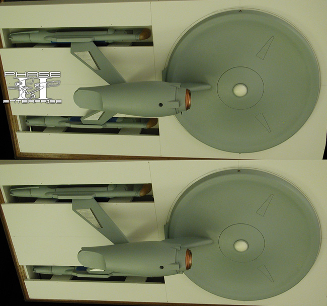
Just an update... yes, this model still exists... no, it isn't finished yet.
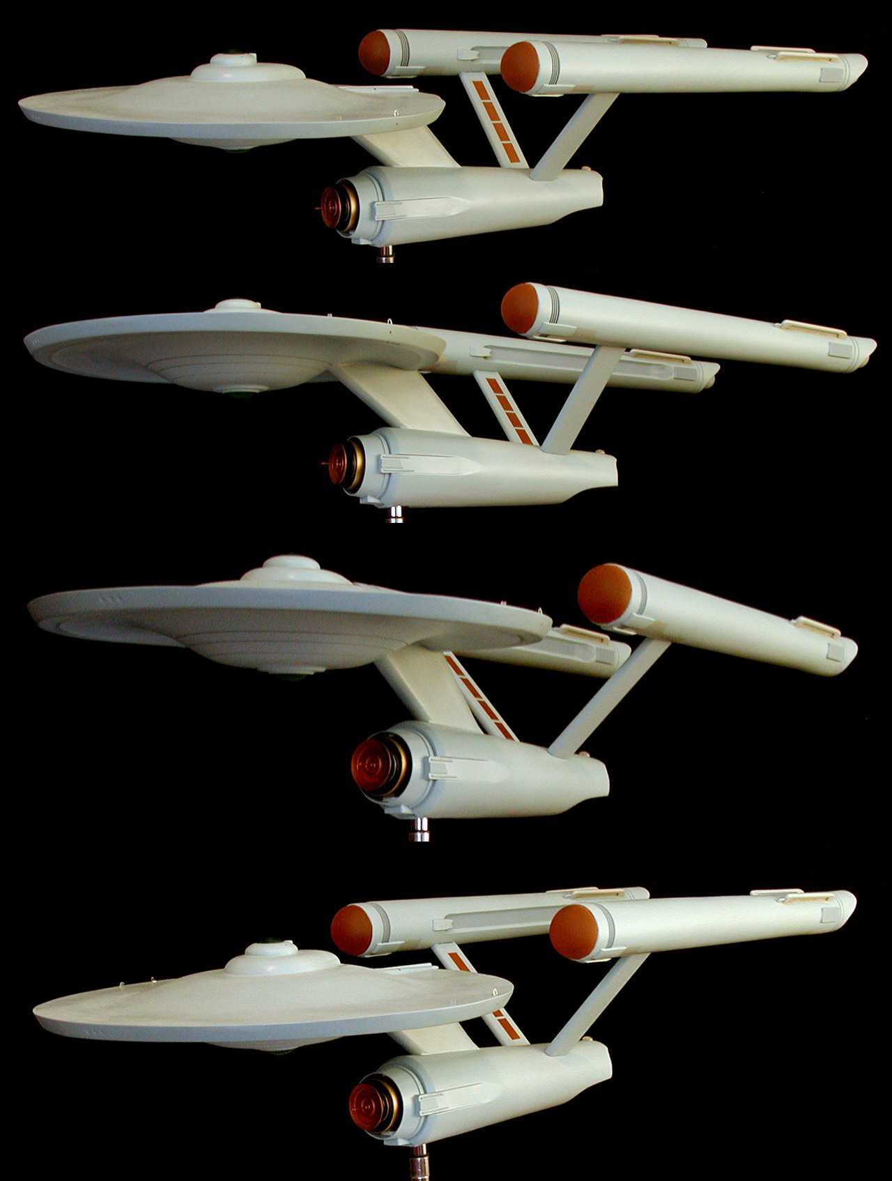
Here is a shot of the model as it stands currently (and how it has looked for the last couple years)...
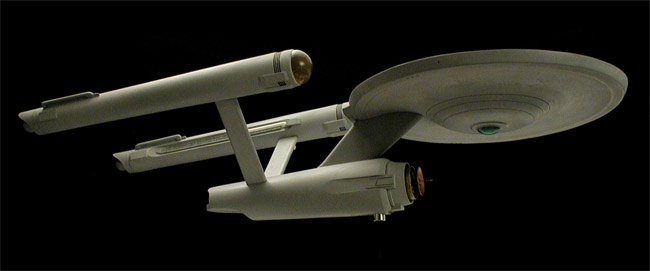
Click to enlarge
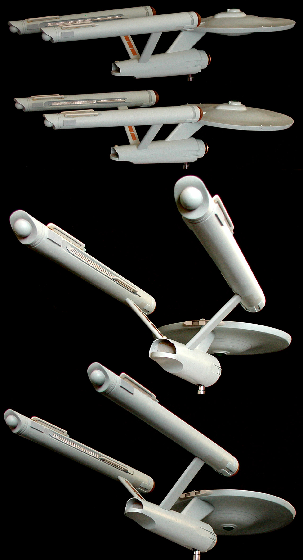
The model is not glued together, it is just sitting assembled. This is how it looks pulled apart...
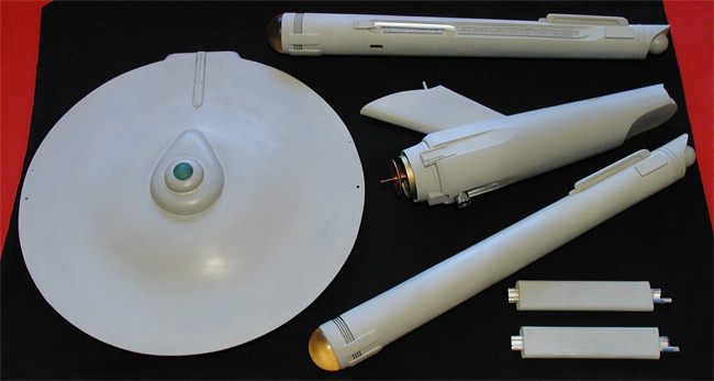
Click to enlarge
I don't know when I can get back to working on it or models in general, but it is one that has survived (at least the final parts). So, hopefully some day it'll stand completed.
Here is a shot of the model as it stands currently (and how it has looked for the last couple years)...

Click to enlarge
The model is not glued together, it is just sitting assembled. This is how it looks pulled apart...
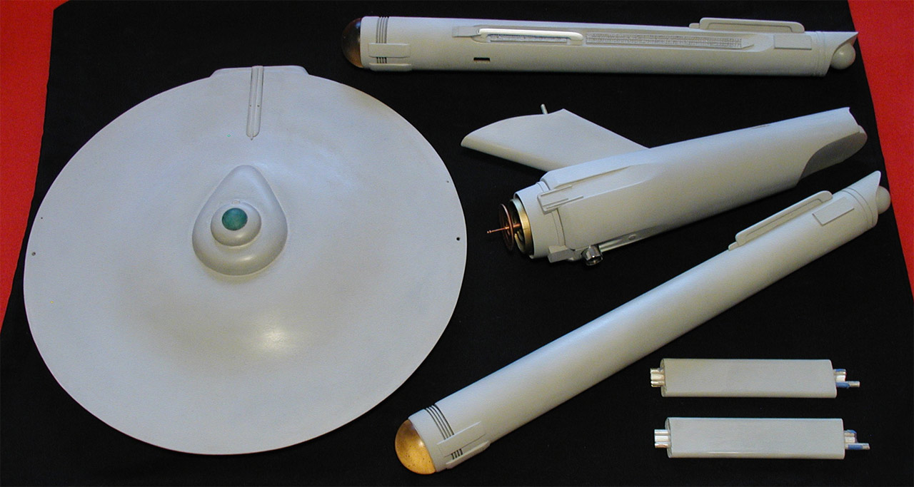
Click to enlarge
I don't know when I can get back to working on it or models in general, but it is one that has survived (at least the final parts). So, hopefully some day it'll stand completed.
-
Richard Baker

- Posts: 16166
- Joined: Tue Feb 07, 2006 10:23 am
- Location: Warrior, Alabama
Re: 33 inch TOS Enterprise - Studio Scale Replica
Just found this thread and have had a great time going through process steps- you have done an excellent job recreating the 33 inch Enterprise (learned a lot about it as well when reading).
"The future is not what it used to be" - G'Kar
Things go wrong and bad things happen- that is just the way the world is-
It is how you deal with it that tells the world who you truly are.
“Censorship is telling a man he can’t have a steak just because a baby can’t chew it.” -Mark Twain
Deviant Art Gallery-
http://phaedrus-3.deviantart.com/
Things go wrong and bad things happen- that is just the way the world is-
It is how you deal with it that tells the world who you truly are.
“Censorship is telling a man he can’t have a steak just because a baby can’t chew it.” -Mark Twain
Deviant Art Gallery-
http://phaedrus-3.deviantart.com/
Re: 33 inch TOS Enterprise - Studio Scale Replica
I would love to see this finished.
Garry AKA --Phoenix-- Rising above the Flames
The Mighty Ten-12 lives.
Star Trek mort. Viva la Star Trek admiraetur.
Olde Phoenix Inn http://www.oldephoenixinn.net
The Mighty Ten-12 lives.
Star Trek mort. Viva la Star Trek admiraetur.
Olde Phoenix Inn http://www.oldephoenixinn.net
-
starseeker
- Posts: 468
- Joined: Tue Mar 28, 2006 9:33 am
Re: 33 inch TOS Enterprise - Studio Scale Replica
Good Lord, Shaw! - welcome back! A couple years ago, I thought sf modellers had lost you forever. An amazing project, an amazing modeller, and an amazing inspiration. Just stumbled across this thread by accident, a bright spot in a bleak week. Thanks!
-
JustPlainJim
- Posts: 692
- Joined: Mon Sep 15, 2008 1:42 am
- Location: Check six
- Contact:
Re: 33 inch TOS Enterprise - Studio Scale Replica
That is one magnificent build! Hats off to you sir.
"The Scots are primarily Celtic &, therefore, 90% insane at birth & genetically predisposed to holding grudges that are, well, genetic & long past their use-by date." - Old Wombat
Re: 33 inch TOS Enterprise - Studio Scale Replica
Thanks for coming back, Shaw
Re: 33 inch TOS Enterprise - Studio Scale Replica
So I have made a little progress over the past few months. I first started in on the final painting of the model...

Click to enlarge
... and then worked on some detailing...
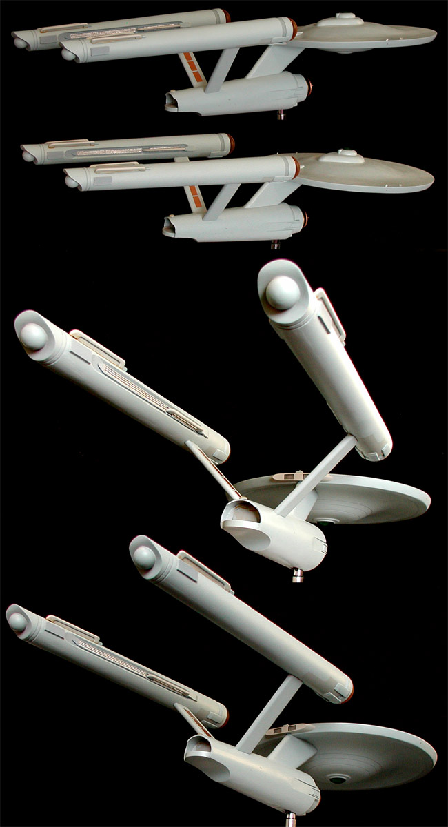
Click to enlarge
Before starting back in on this, my wife asked me to start on something a bit smaller, so I scratch built a couple of Phaser I props...
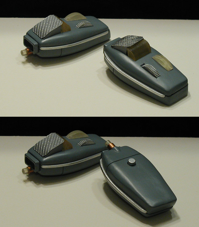
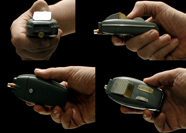
Anyways, I know these images aren't a massive change from when the model was just covered in primer, but it was a series of big steps for me.
Click to enlarge
... and then worked on some detailing...
Click to enlarge
Before starting back in on this, my wife asked me to start on something a bit smaller, so I scratch built a couple of Phaser I props...
Anyways, I know these images aren't a massive change from when the model was just covered in primer, but it was a series of big steps for me.
Re: 33 inch TOS Enterprise - Studio Scale Replica
Nice phaser one models.
Not many people know that when the phaser originally conceived Roddenberry proposed a pop up targeting display that was the grid. If you look closely at the episode, The Man Trap, you can see this when they fire their phasers.
I guess the idea was dropped due to the props breaking during use.
Not many people know that when the phaser originally conceived Roddenberry proposed a pop up targeting display that was the grid. If you look closely at the episode, The Man Trap, you can see this when they fire their phasers.
I guess the idea was dropped due to the props breaking during use.
"Nothing to do now but drink a beer and watch the universe die."
"Basically what I do everyday."
I AM Spartacus!
I'm Batman.
Don't believe everything you see on the Internet!- Abraham Lincoln
Oh my God!! It's full of plastic peanuts!
Today is a good day to model!
"Basically what I do everyday."
I AM Spartacus!
I'm Batman.
Don't believe everything you see on the Internet!- Abraham Lincoln
Oh my God!! It's full of plastic peanuts!
Today is a good day to model!