
OK gang....I'm looking at doing a 1:32 scale model of the Mk III Viper as seen in B&C. I'm gauging size off of the Mobius Mk II and assuming an increase of relative size of about 25%, so no reusing bits from that kit.
What I'm really concerned about, is how to build the nose? Do I just rough it out from a solid wooden block then cover it with the almighty AVES (just ordered a pound of it) this would make having a cockpit and gear wells somewhat problematic.....
or perhaps a basically 4 sided pipe made up of say .080 styrene with the correct profile from the side and above then sand to shape.....
OR perhaps a frame of bulkheads and longitudinal members, skinned with something like .040 styrene with AVES applied as needed to fill gaps and provide proper contour....
Or how bout something I've not thought of?
Needing a little feedback......
Moderators: Joseph C. Brown, Moderators
Needing a little feedback......
I Stay away from Discussions of Religion, Politics, and Star Wars...all for the same reason......
-
Mr. Badwrench

- Posts: 9587
- Joined: Fri Jul 12, 2002 6:31 pm
- Location: Wheatridge, Co.
-
Tankmodeler
- Posts: 949
- Joined: Fri Jul 30, 2010 12:04 am
- Location: Ontario
-
kenlilly106
- Posts: 1302
- Joined: Sun Jan 14, 2007 12:18 am
- Location: in the mountains
Yeah I was leaning strongly toward that option anyways. while not the easiest route its prolly the cheapest as I haveall the materials on hand already, plus I have done projects in that way before ( a BC-304 that won Bronze at WF in '08) plus I think its neat seeing the way they go together....
In this case I'm seeing three major sub assemblies.......the engine portion......a cockpit module......and the nose.........
In this case I'm seeing three major sub assemblies.......the engine portion......a cockpit module......and the nose.........
I Stay away from Discussions of Religion, Politics, and Star Wars...all for the same reason......
I have built both the solid version, albeit, with bulkheads, and the spaces between frames filled with A+B Epoxy (similar to Aves), and have built skinned versions.
You *can* do the solid version and still have a cockpit (or landing gear bays, pod bays, etc, etc.) but you must build, at least, the space for the bay or cockpit before the framing the rest of the body/hull/fuselage. The one big plus to this plan is that you find out that the interior is 10% larger than the exterior early on, a problem with virtually every pop-media sci-fi vehicle.
On the other hand, you can build the frame and skin it, then mark openings in the exterior, and cut them open. I have substantial success with that. BUT, any interiors you want to make for it, must drop in. If you're willing to plan some, you can build your model in halves. Its a simple change to the build. Cut two main profiles instead of one, and attach frames to each profile, and skin each half.
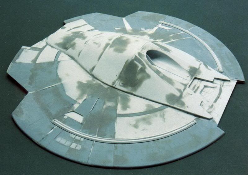
Here's the bottom hull of one of my projects:
http://i88.photobucket.com/albums/k170/ ... n/0030.jpg
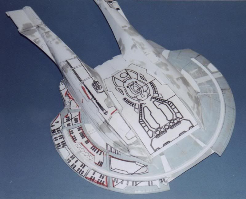
Here's the top of half:
http://i88.photobucket.com/albums/k170/ ... n/0046.jpg
I can now build a shuttle bay between the hulls.
Finally, 40 thou is painful to coax around anything but the mildest of curved forms. I would recommend 15 thou for anything around 2cm in radius. 20 thou for larger radii.
You *can* do the solid version and still have a cockpit (or landing gear bays, pod bays, etc, etc.) but you must build, at least, the space for the bay or cockpit before the framing the rest of the body/hull/fuselage. The one big plus to this plan is that you find out that the interior is 10% larger than the exterior early on, a problem with virtually every pop-media sci-fi vehicle.
On the other hand, you can build the frame and skin it, then mark openings in the exterior, and cut them open. I have substantial success with that. BUT, any interiors you want to make for it, must drop in. If you're willing to plan some, you can build your model in halves. Its a simple change to the build. Cut two main profiles instead of one, and attach frames to each profile, and skin each half.
Here's the bottom hull of one of my projects:
http://i88.photobucket.com/albums/k170/ ... n/0030.jpg
Here's the top of half:
http://i88.photobucket.com/albums/k170/ ... n/0046.jpg
I can now build a shuttle bay between the hulls.
Finally, 40 thou is painful to coax around anything but the mildest of curved forms. I would recommend 15 thou for anything around 2cm in radius. 20 thou for larger radii.
VERY NICE AKIRA!!!!!! Thats the kinda build I like to do!!!! What scale is that in?
As for the .040 I wasn't thinking of using it as a wrapper, but doing the curves along the longitudinal axisin 8 facets then using Aves and some sanding to get the final contour around the diameter.....
As for the .040 I wasn't thinking of using it as a wrapper, but doing the curves along the longitudinal axisin 8 facets then using Aves and some sanding to get the final contour around the diameter.....
I Stay away from Discussions of Religion, Politics, and Star Wars...all for the same reason......
Check out the different techniques this fella uses to scratch-build hollow star-ship hulls that have complex curves. very educational
LINK
I suggest going through the first few pages of each build to get an idea of what he does. Just scroll down a bit and you'll see the links to all the different pages of the builds - under the pictures of the ships.
LINK
I suggest going through the first few pages of each build to get an idea of what he does. Just scroll down a bit and you'll see the links to all the different pages of the builds - under the pictures of the ships.
I must not fear. Fear is the mind killer. Fear is the little-death that brings total obliteration.
Hopefully this link will work:Chief 400 wrote:VERY NICE AKIRA!!!!!! Thats the kinda build I like to do!!!! What scale is that in?
As for the .040 I wasn't thinking of using it as a wrapper, but doing the curves along the longitudinal axisin 8 facets then using Aves and some sanding to get the final contour around the diameter.....
http://s88.photobucket.com/user/ajmadis ... nstruction
without requiring you to be me.
The Akira is 1/800. There are some serious contour issues with it that are very difficult to fix. The sides of the upper hull are too shallow. And the armor & port hole details on the main hull took me years to solve. Basically involved creating custom punch & die sets. I was going to start over at 1/1000 scale. Most of the time in the build was analyzing the references and figuring out how various sub-assemblies were shaped in 3 dimensions. So the second build would go fairly quickly, but my USS Thunderchild project ended up behind some other projects.
If I understand what you're saying. What you really want to do, is a series of laminations with 40 thou sheet. Then smoothing out the "terraces" with some filler. I have done that. Even on the Akira.
http://i88.photobucket.com/albums/k170/ ... n/0021.jpg
If you look at the lower right, at the forward edge where the catamaran meets the upper hull, you'll see what looks like a plug of grey filler. There is a series of sheet styrene pieces cut to fit that triangle. The first piece on the primary hull matches the desired shape as the pontoon meets the hull. Then additional layers are added on top of the first piece that gradually changes to match the profile higher on the catamaran. Then filler was sculpted on top of the laminations to create a smooth shape.
ooooh yeah man that is the ticket........
Love the way the catamarans came up, what didja use to skin those suckers? Thats pretty much what I had envisioned on the viper nose. Truley an inspirational build....
Heres to hoping the packages I have floating around out there hit dirt today so I can start cutting styrene this weekend!
Love the way the catamarans came up, what didja use to skin those suckers? Thats pretty much what I had envisioned on the viper nose. Truley an inspirational build....
Heres to hoping the packages I have floating around out there hit dirt today so I can start cutting styrene this weekend!
I Stay away from Discussions of Religion, Politics, and Star Wars...all for the same reason......
The front of the pontoons where there are mild complex curves, are skinned in 15 thou sheet. The main body of the catamarans are skinned in 20 thou.Chief 400 wrote:ooooh yeah man that is the ticket........
Love the way the catamarans came up, what didja use to skin those suckers? Thats pretty much what I had envisioned on the viper nose. Truley an inspirational build....
Heres to hoping the packages I have floating around out there hit dirt today so I can start cutting styrene this weekend!
If it is not obvious, be certain to add glue tabs between panels. Does require some planning. Before just gluing the first panel on, glue tabs to its future interior side where possible. There are no glue tabs where the panels meet the modified Enterprise-D hull. Do not try and build your model like a real ship or a stick frame house, meaning trying to get your panels edges to line up on framing edges.
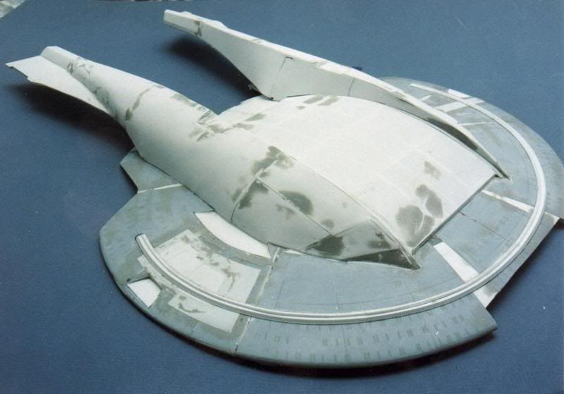
Here is another project built with an interior frame and then skinned:
http://s88.photobucket.com/user/ajmadis ... nstruction
On this project, I wanted to put a "cockpit" interior in it, which could be revealed by pulling a panel off, like an old Aurora model, or in this case, the oversized canopy. And everything looked good until I took the overhead (studio) set plan and reduced it to 1/72 scale. And discovered, like with virtually all popular media sci-fi subjects, that the interior design only vaguely resembles the exterior. In this case, the ledge the canopy sits on interferes with the studio set walls. To get the interior to fit, would require reducing it to approximately 1/150 scale. I have contemplated faking out some sort of cockpit, which would be visible through the "windscreen" of the canopy, but ran out of energy for the project.
I really should finish it. This was a project that was easy to initially frame, but like all of my other efforts, a subtle but important detail brings progress to a halt. The impulse drive emitters have a complex shape just to fit into the notch in the "wngs". To then add the vane detail oriented parallel to the main axis, with the grooves perpendicular to the wing anhedral was very challenging. That's why there are so many pictures of different versions of the impulse drive emitters.
Last edited by ajmadison on Sun Apr 07, 2013 9:46 am, edited 1 time in total.
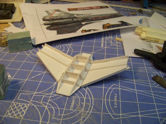
Yep, took stock yesterday and I gots .020 in stock as well. Like the idea of glue tabs, I can see a definate need for that. I started out on a little project yesterday using leftover bits laying on the bench just to exercise the skills a bit.......
http://i1353.photobucket.com/albums/q66 ... e53ec0.jpg
Give myself a little room for frakups since I don't know what this critter is gonna look like. Thinkin I might start work on a cockpit tub next then build the nose around it......
Wahts an easy way to make recessed panels with rounded corners?
http://i1353.photobucket.com/albums/q66 ... e53ec0.jpg
Give myself a little room for frakups since I don't know what this critter is gonna look like. Thinkin I might start work on a cockpit tub next then build the nose around it......
Wahts an easy way to make recessed panels with rounded corners?
I Stay away from Discussions of Religion, Politics, and Star Wars...all for the same reason......
Not exactly sure what you mean. If you're talking about something that in its extreme, resembles an egg cartoon, this can be tricky. You'll need to cut the rectangle with rounded corners out of the most exterior sheet first. That means almost cutting to the corners, then scribing the arc of the fillet. A pair of dividers can help with that. Since the interior of the rectangle is scrap/waste, you can find the center of the arc with the dividers, then using that center point, scribe the arc of the fillet.Chief 400 wrote:Yep, took stock yesterday and I gots .020 in stock as well. Like the idea of glue tabs, I can see a definate need for that. I started out on a little project yesterday using leftover bits laying on the bench just to exercise the skills a bit.......
http://i1353.photobucket.com/albums/q66 ... e53ec0.jpg
Give myself a little room for frakups since I don't know what this critter is gonna look like. Thinkin I might start work on a cockpit tub next then build the nose around it......
Wahts an easy way to make recessed panels with rounded corners?
Another alternative, is this:
http://s88.photobucket.com/user/ajmadis ... 2.jpg.html
Look at the lower warp nacelle. There is supposed to be a fillet in the lower right corner of the bussard collector regulator housing. Since this was a resin model, I didn't want to remove the entire housing and rebuild it, I made my own fillets, and applied them individually into the angled cut.
The fillets are kinda annoying to make. Cut a strip of sheet styrene as wide as the fillet. As wide as the fillet. This means the distance across the 45 angled line between the sides of the panel. Then using a dowel or evergreen rod with sand paper wrapped around it, a round needle file, whatever has the correct radius for the fillet, abrade the end of the strip to take the desired radius of the fillet. THEN, make the cuts around the fillet to produce the angled cuts that produces a deformed triangle that fits into the angle/rectangle of interest. There will be MANY parts that do not look quite right and must be discarded. For the 1:1000 Refit-E garage kit pictured, I probably made 4 parts for each one installed.
If there is one piece of advice that every new scratchbuilder should understand, is that despite photographs showing a complete sub-assembly all built up, there are potentially dozens of parts or even sub-assemblies, that have been discarded because they are wrong some how: doesn't fit, has serious orthogonal issues, doesn't look like the prototype, not enough glue, too much glue, etc. I personally plan on building any sub-assembly at least twice, and am happy when one try is enough.
On the other hand, for simple boxes that are measured in centimeters (lately I'm building lots of parts that are measured in millimeters, ugh) I can crank out a sub-assembly in a few minutes. I can then modify that box fairly quickly. I can knife off the join between two panels in a minute, sand that angle, and apply a flat strip to that void to produce a 45 degree fillet between those facets. So I can try various looks and ideas in a few minutes. My point is that with practice, you can count on being able to build certain objects quickly and easily and be happy with the results.